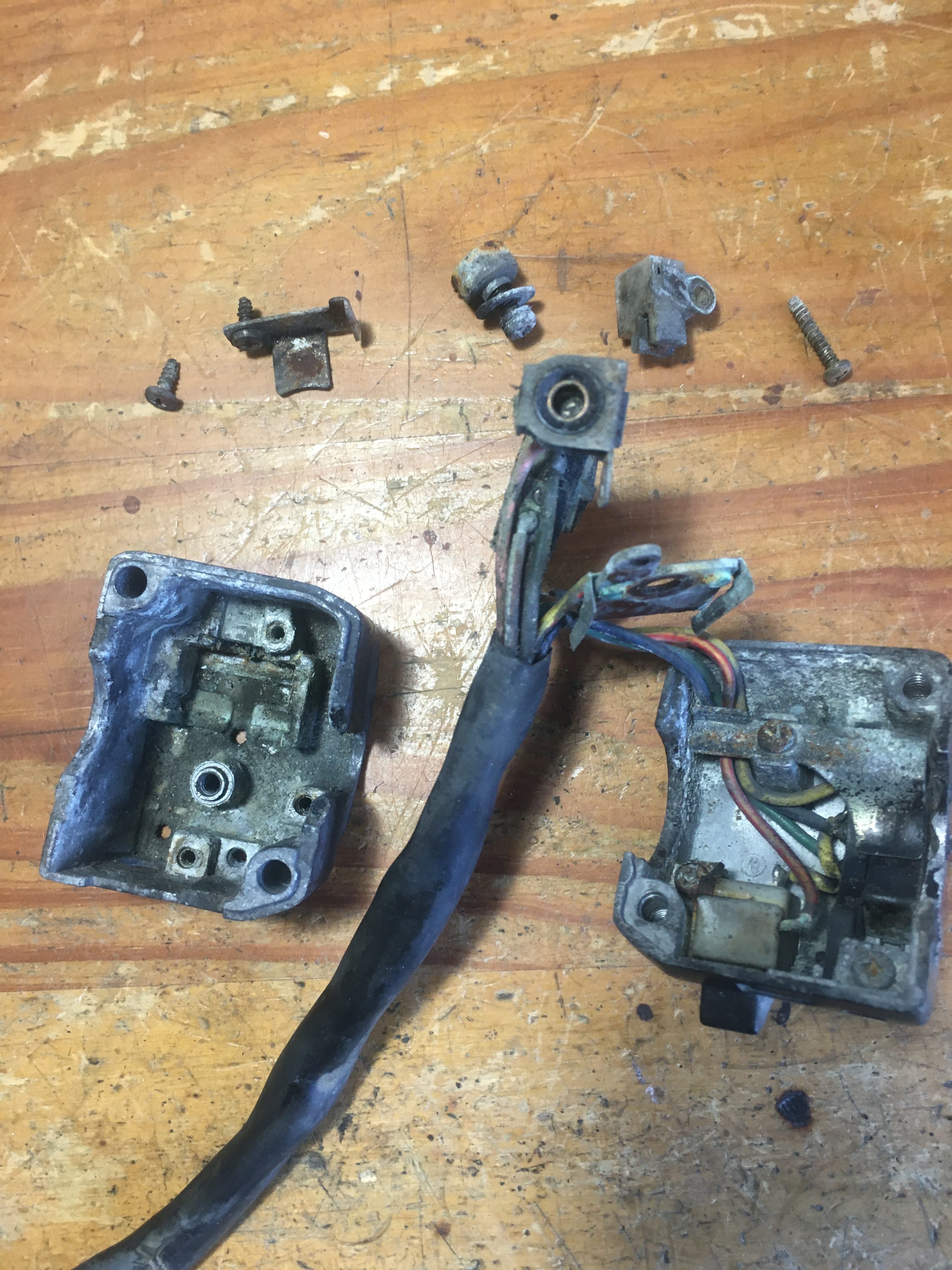
Here are the left and right switchgear from the donor bike.
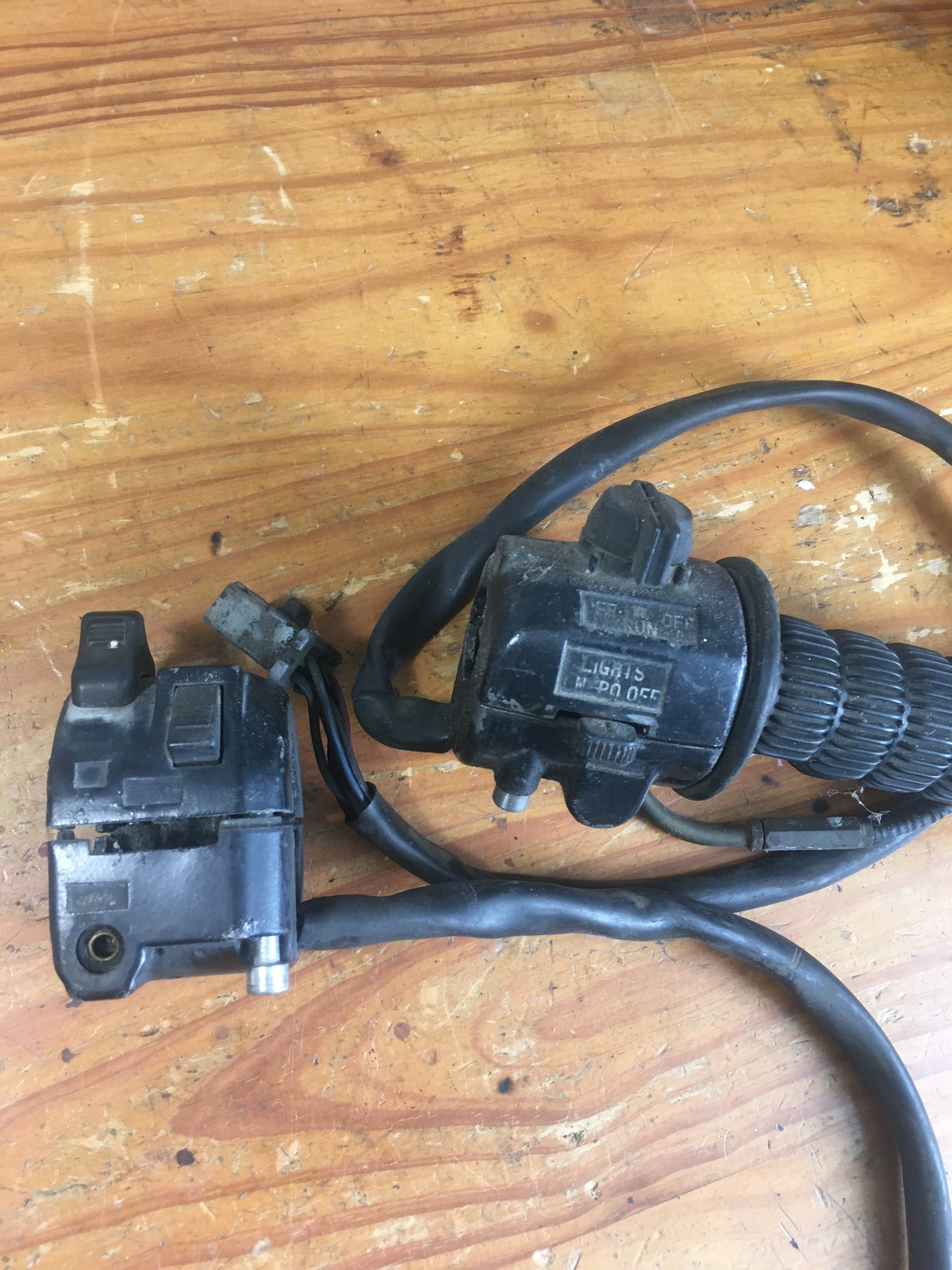
Straight away we can see that I am missing a horn button and indicator rocker (and probably internals), from the LHS, and the RHS stop switch is missing it’s red insert.
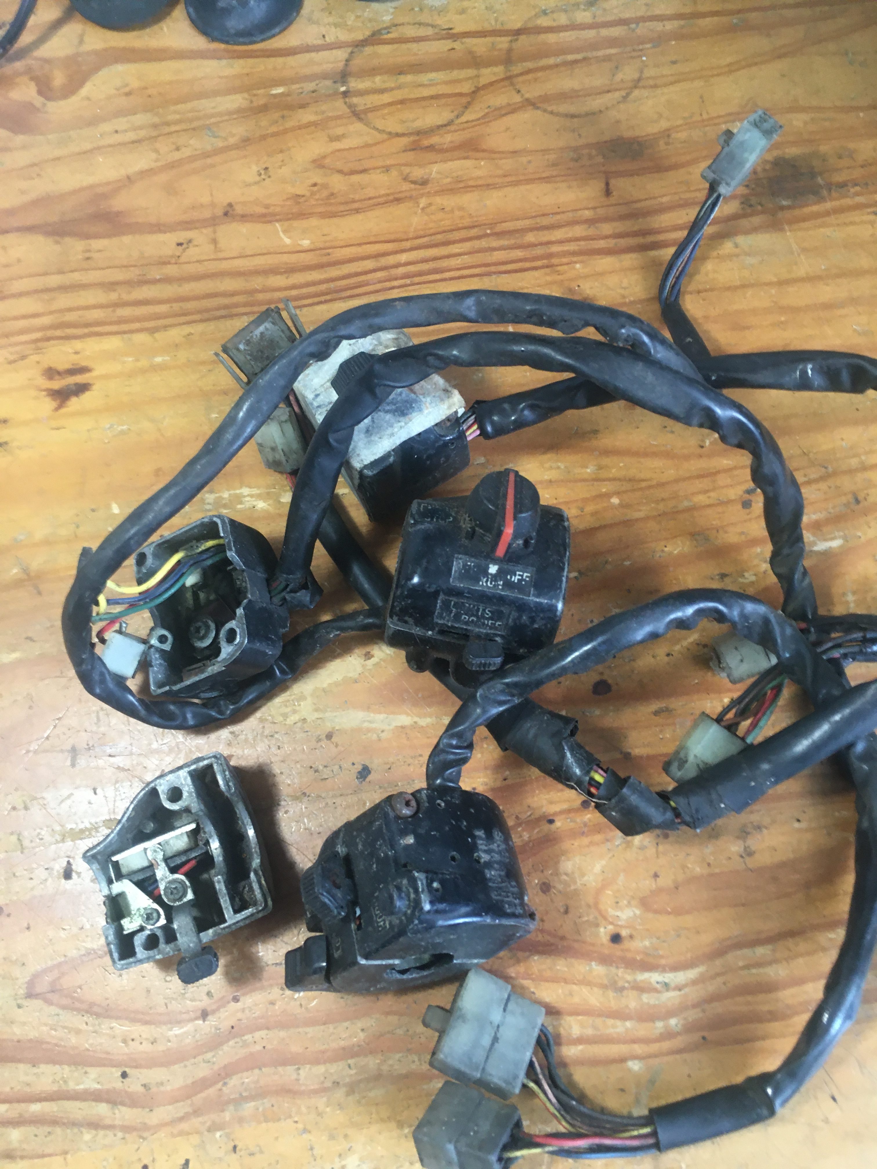
the second picture, of all the Parts box retrievals show that i have enough there to make repairs hopefully.
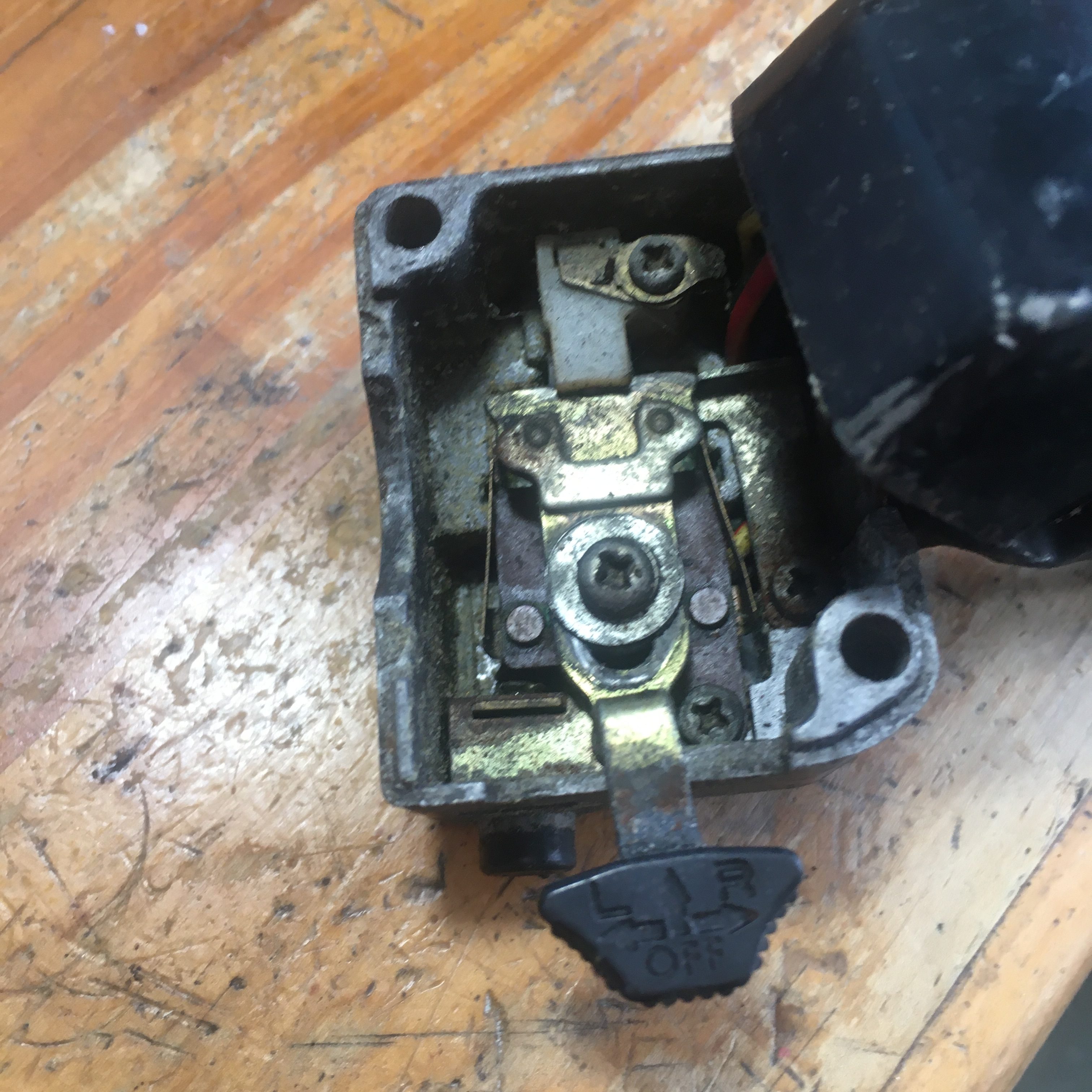
Opening up the Right hand switch showed no nightmares, and replacement of the kill switch mechanism was the work of 3 screws and a few minutes.
The left hand switch was another matter.

Looks pretty dirty 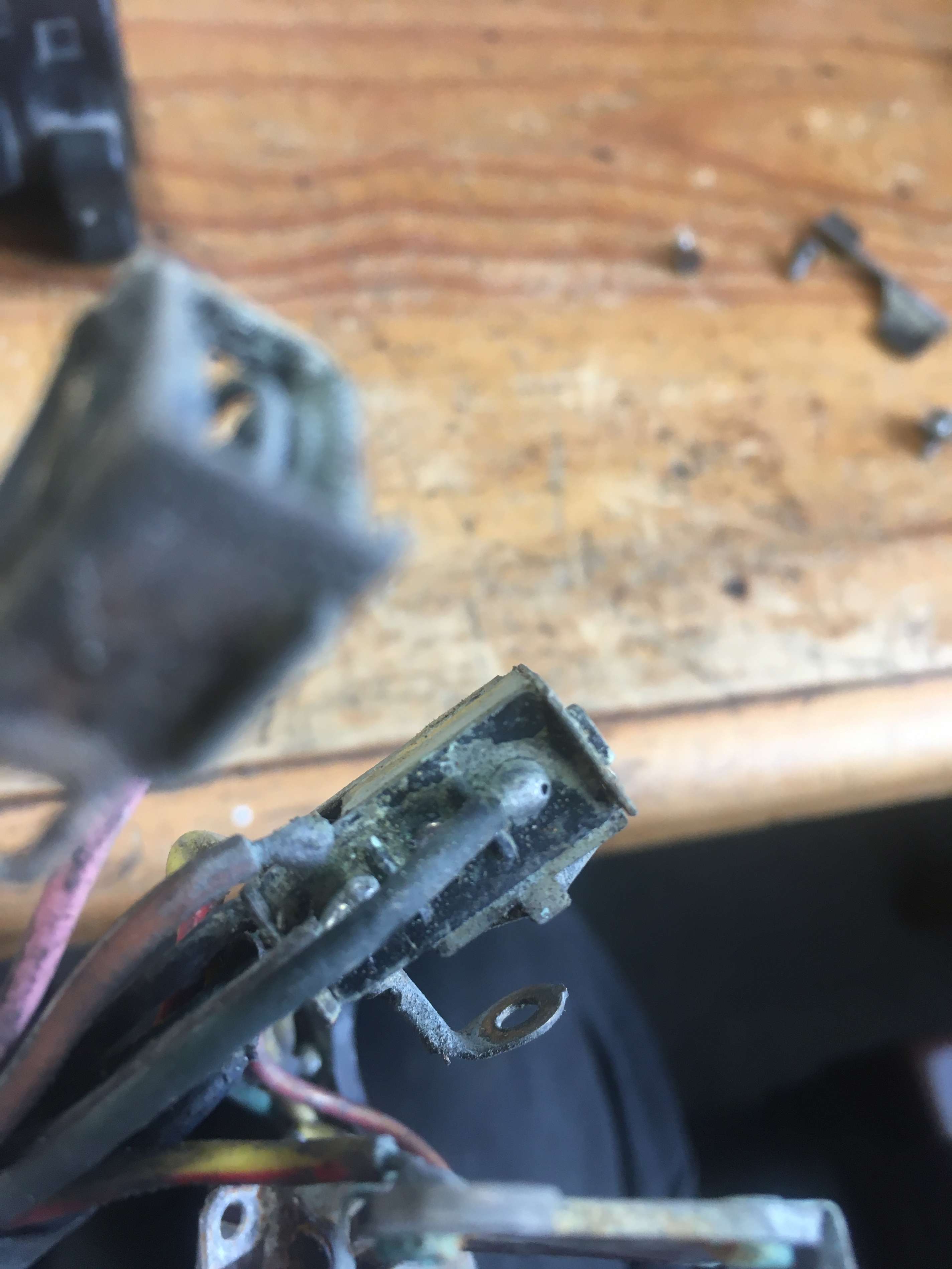
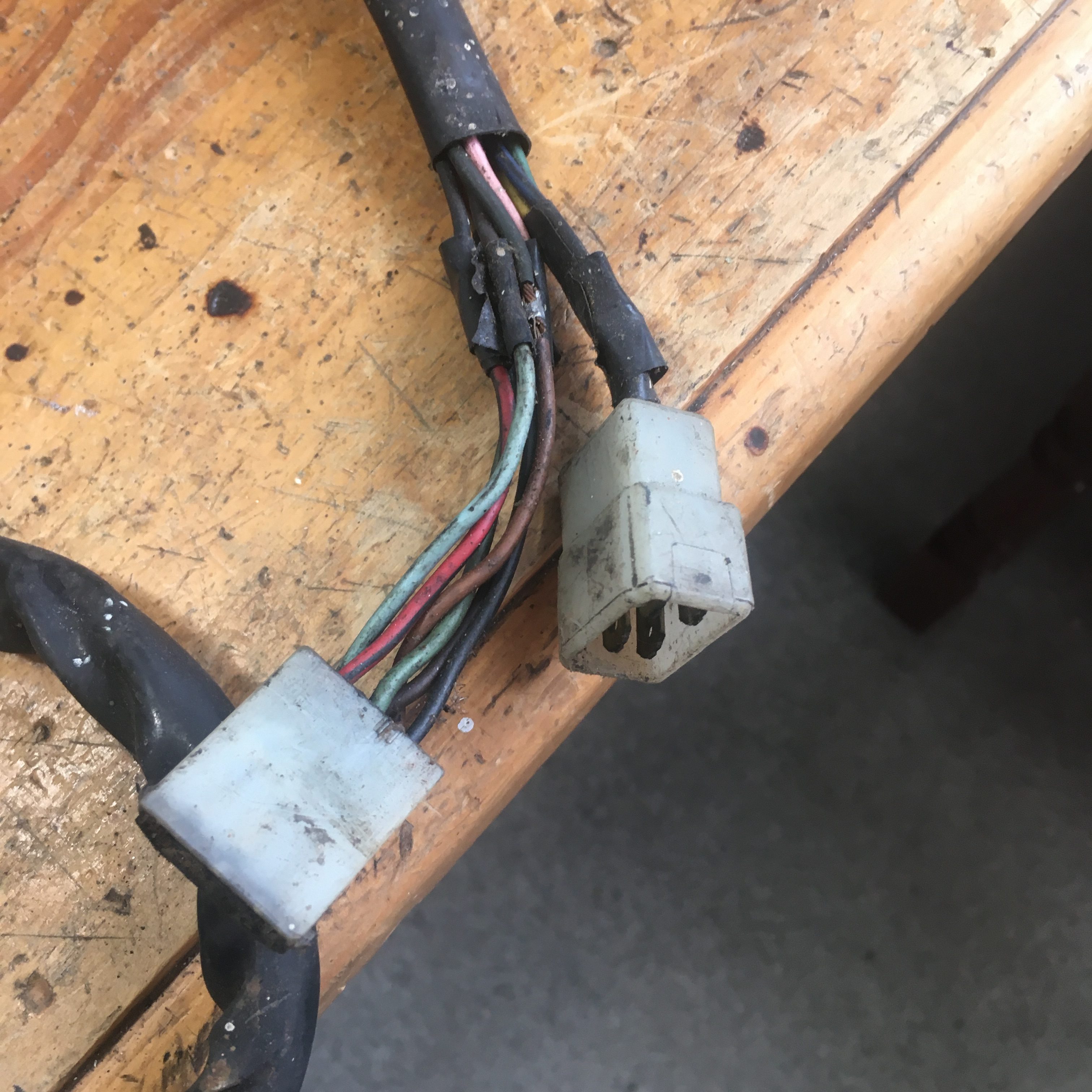
Unsoldered wire 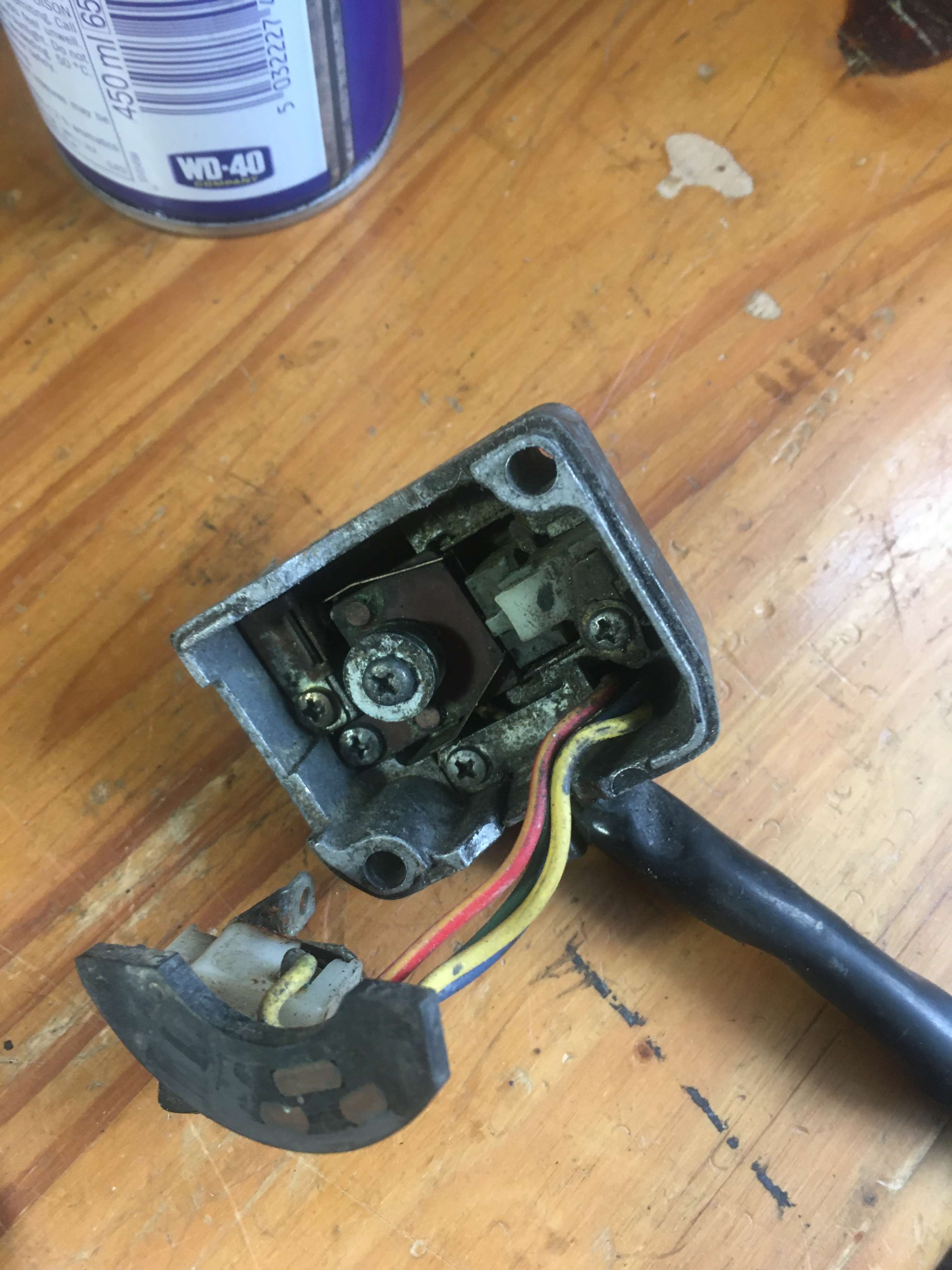
Another set of wired internals
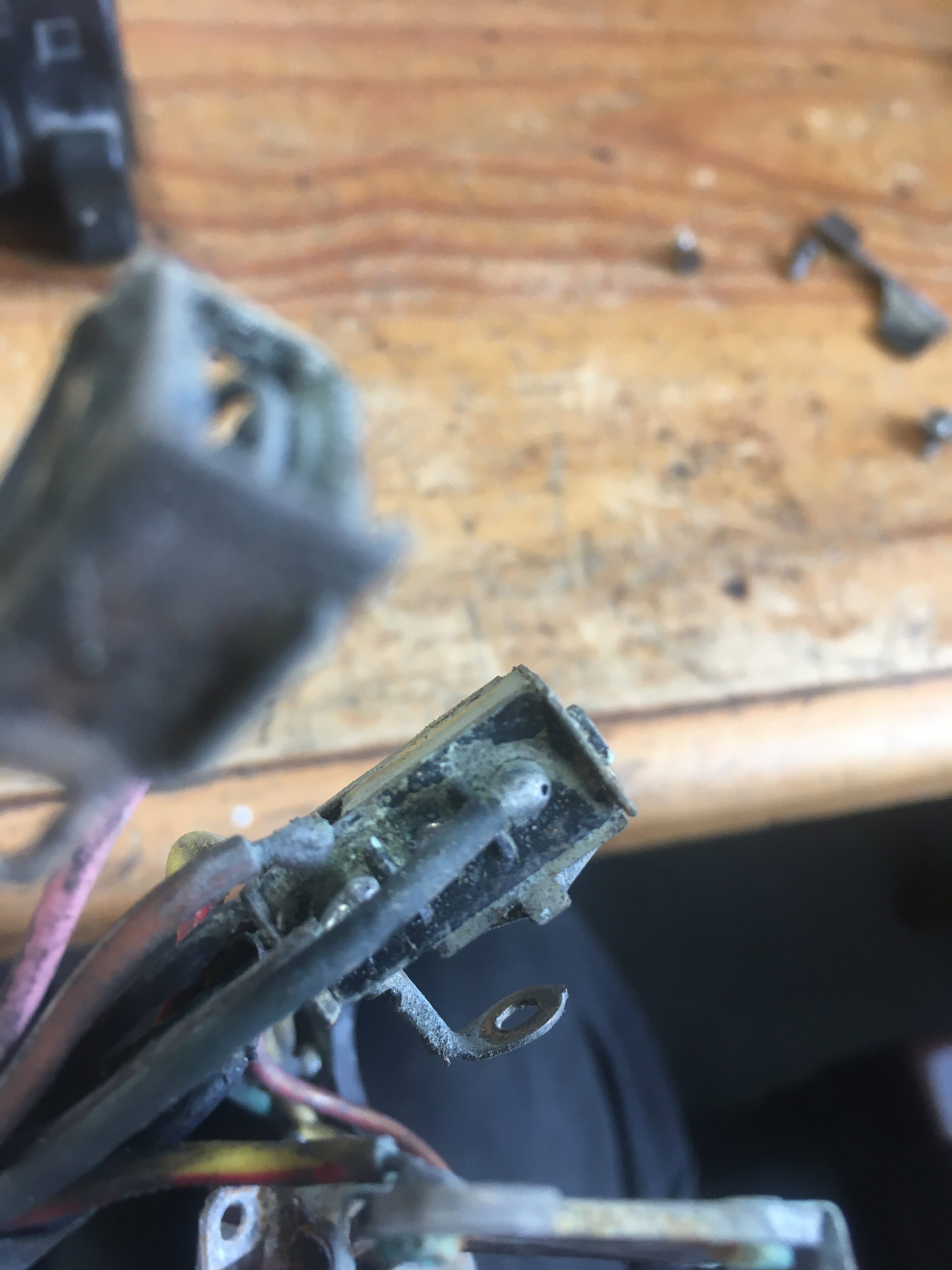

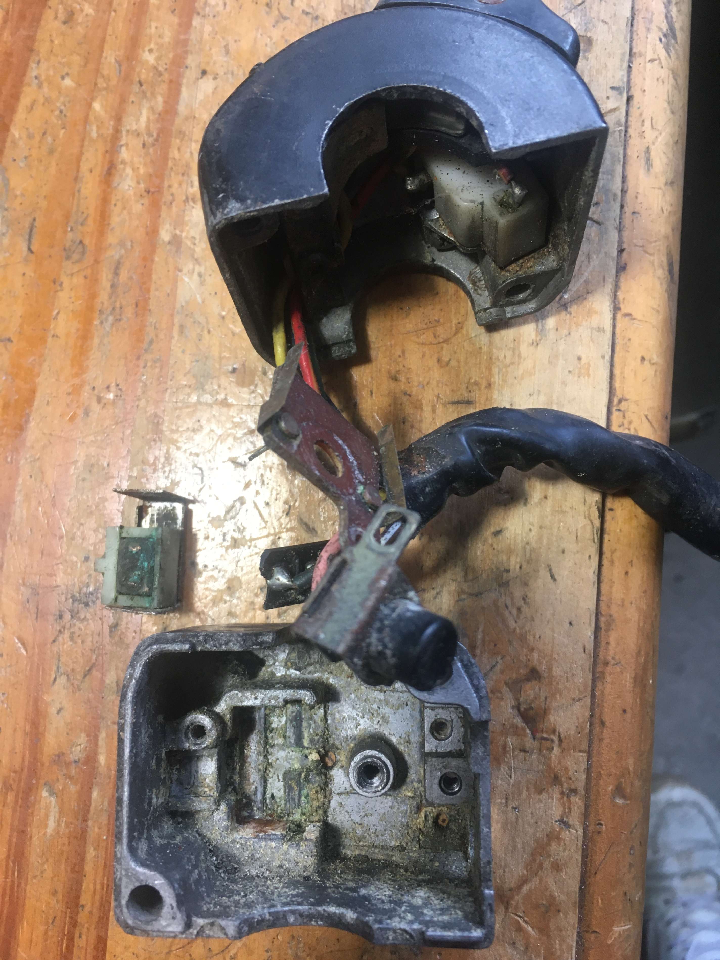
The internals were filthy, and when disassembled… proved to be corroded everywhere.
One of the wires for the indicator switch had come unsoldered, and I didn’t fancy my chances of re-soldering with such a small attachment area and the green corrosion.
fortunately, i have another set of internals, with the correct connectors on the end of the wires.
combining three sets of switch-gear, (to get the horn button as well), will be enough to make one good one.
first step is to remove everything from a pair of switch-gear shells, and give them a bit of a clean.
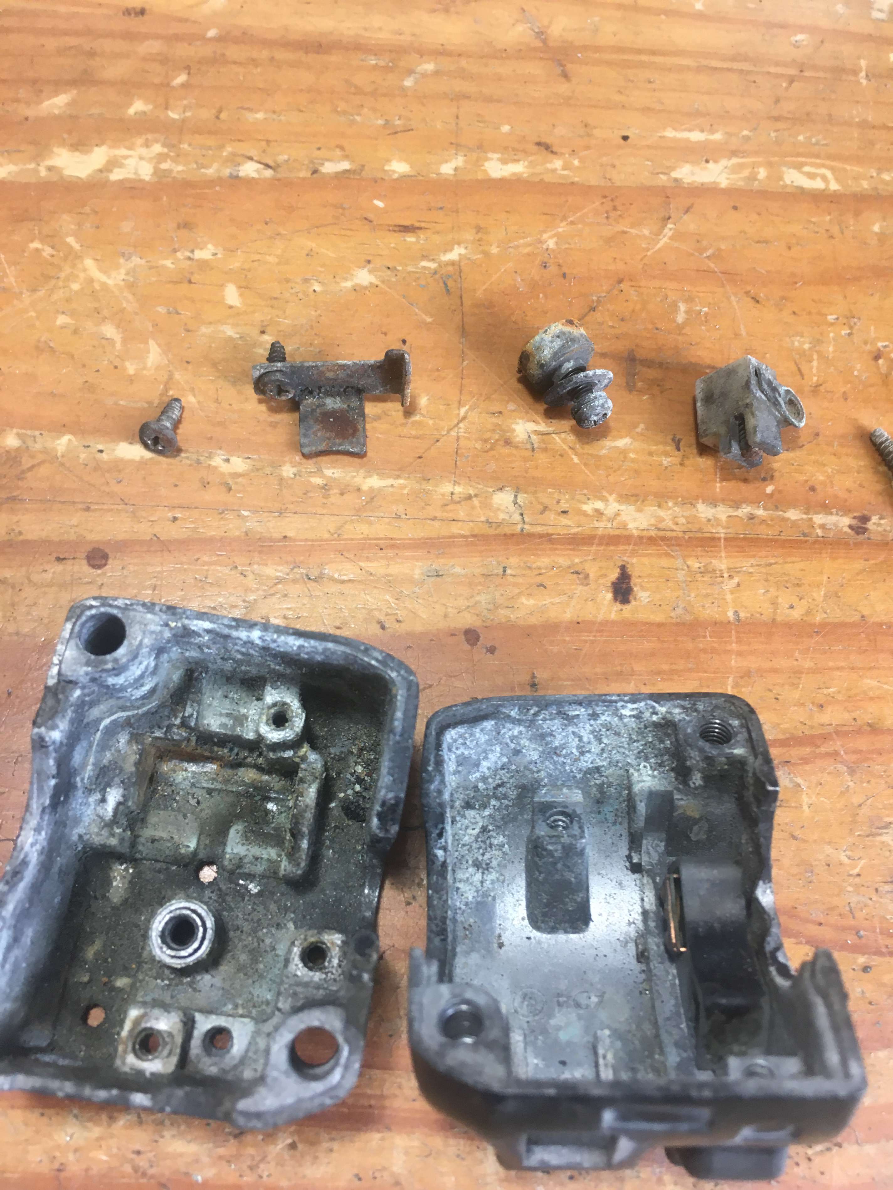
Before 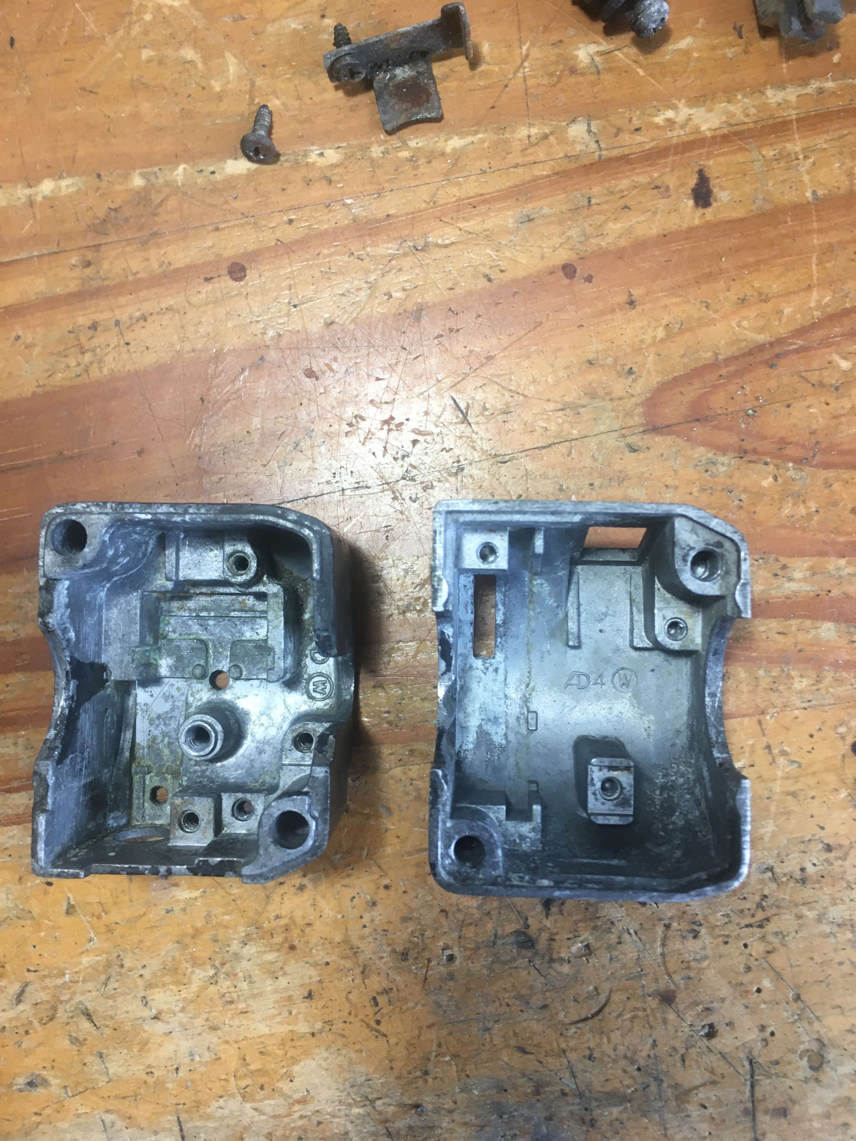
After


Cleaning was done in a paraffin batch with a variety of brushes, scrapers, abrasives, and a final spray with brake cleaner.
Assembly will be with Vaseline petroleum jelly as lubricant, with a splash of WD40 on conducting surfaces.
When we get around to the full cosmetic build, the switch-gear will be candidates for blasting and respraying.
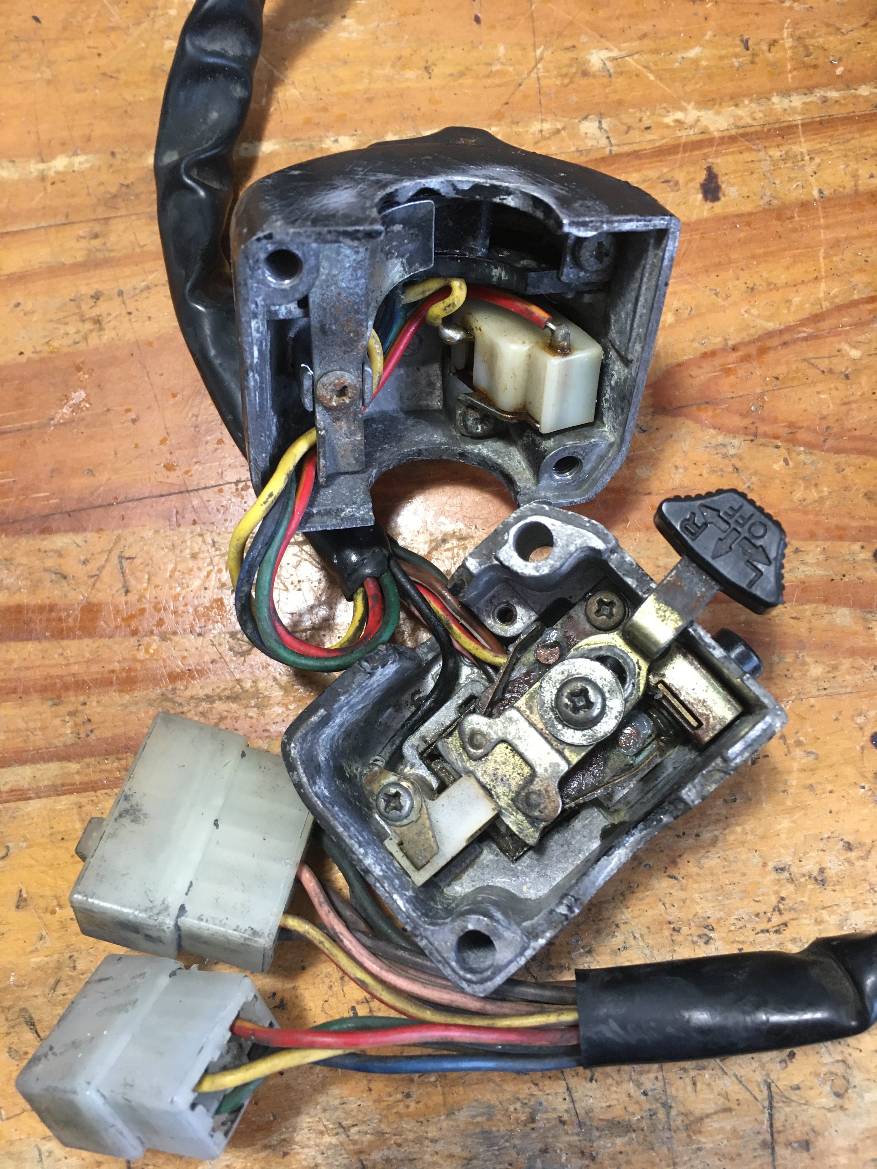
On opening up the spare switch-gear bottom, I found more desoldered wires.
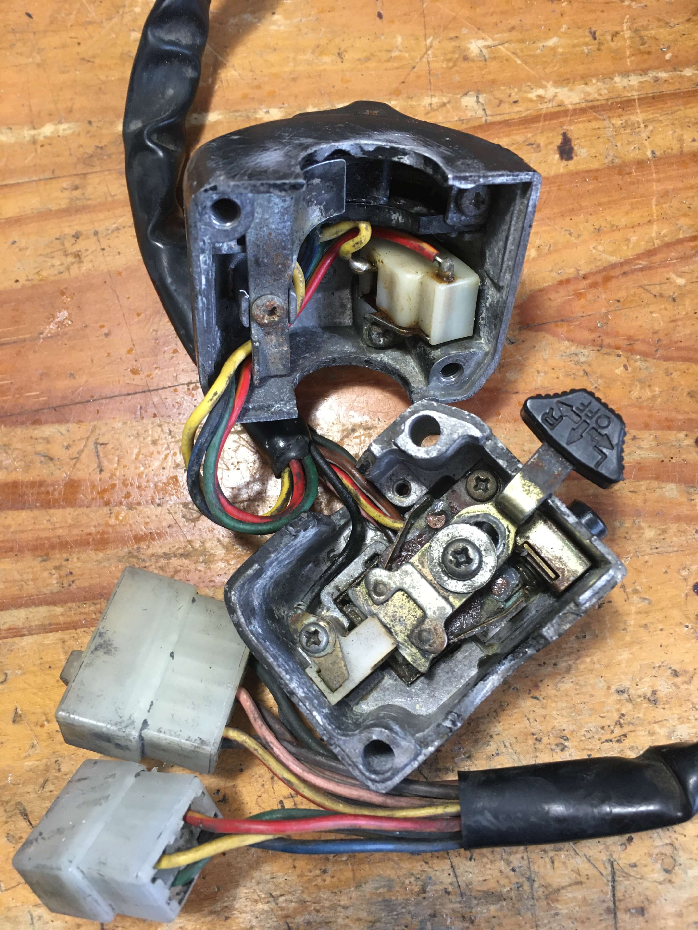
Lets have a look at the next candidate. The one with the intact horn button.
This appears largely intact, but the downside is that the connectors at the end of the wires have suffered a degree of bodgery, and now sport one incorrect connector, and one correct connector with the wrong coloured wires.
It looks to have been modified to fit an XS250.
On opening up, it all initially looked good, but as soon as I touched the indicator switch connector block, the wires stayed soldered, but the connector block plastic fell to pieces.
I now have a situation where I have no way to simply assemble a working switch out of the available parts.
I’m going to have to attempt some soldering!
…
So the soldering went well. I had to re-solder a wire to the plastic connector block which houses the actual sliding indicator switch, and it went rather well.
I cleaned the contact with some 400 wet-n’-dry, used lakes of flux, and it just popped on.
Soldering the horn wire on was a different matter. The pink horn wire was so blackened with corrosion, even a couple of centimetres down the insulation, that solder wouldn’t stick to the wire despite cleaning up with abrasive.
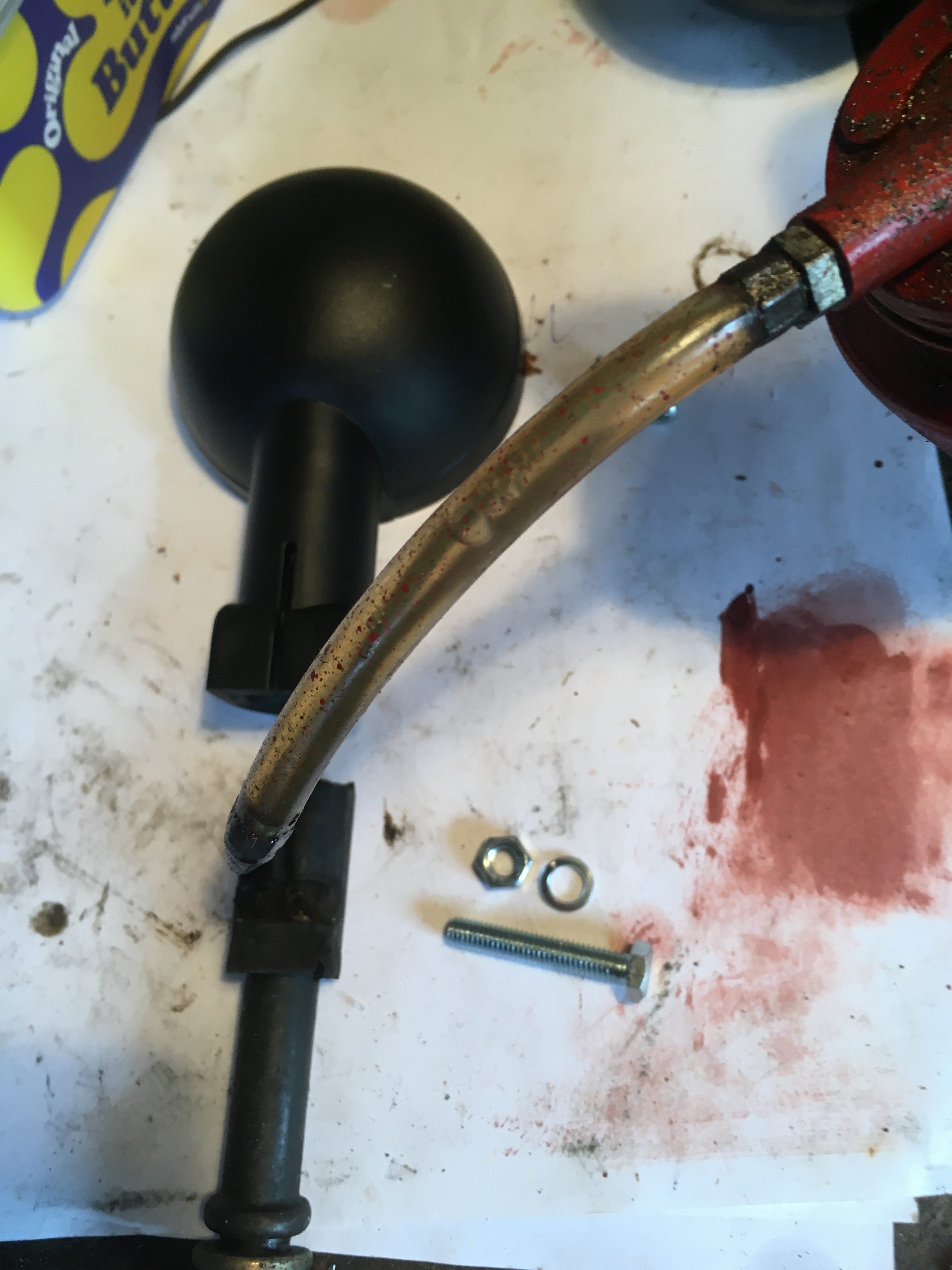
I snipped the horn, and a length of wire from the spare, and then crimped the pink horn wires together rather than soldering.
Then I put it all back together again into the cleaned switchgear shells, with WD40 and vaseline.
Done 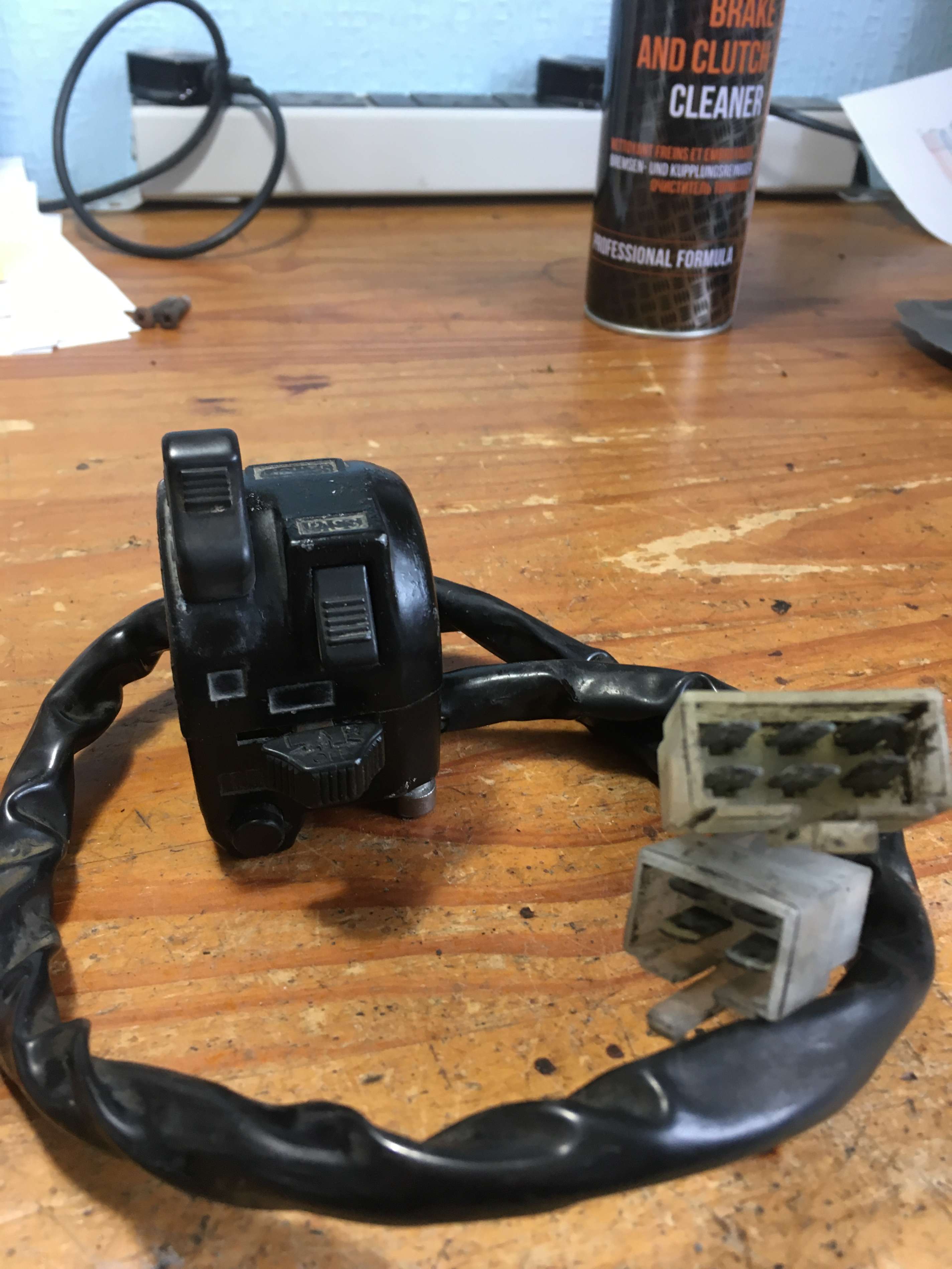
Good enough 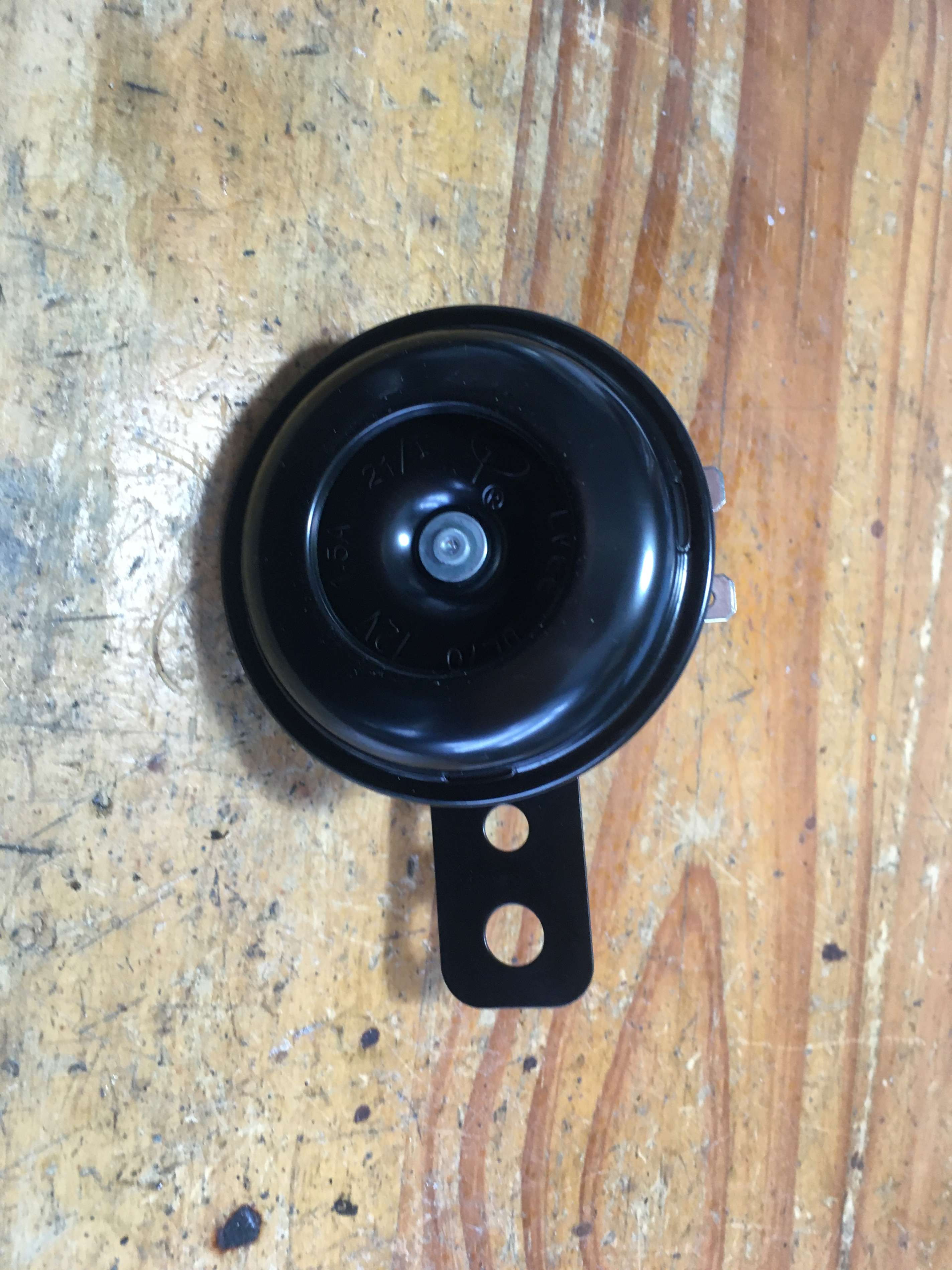
…and my new horn arrived today


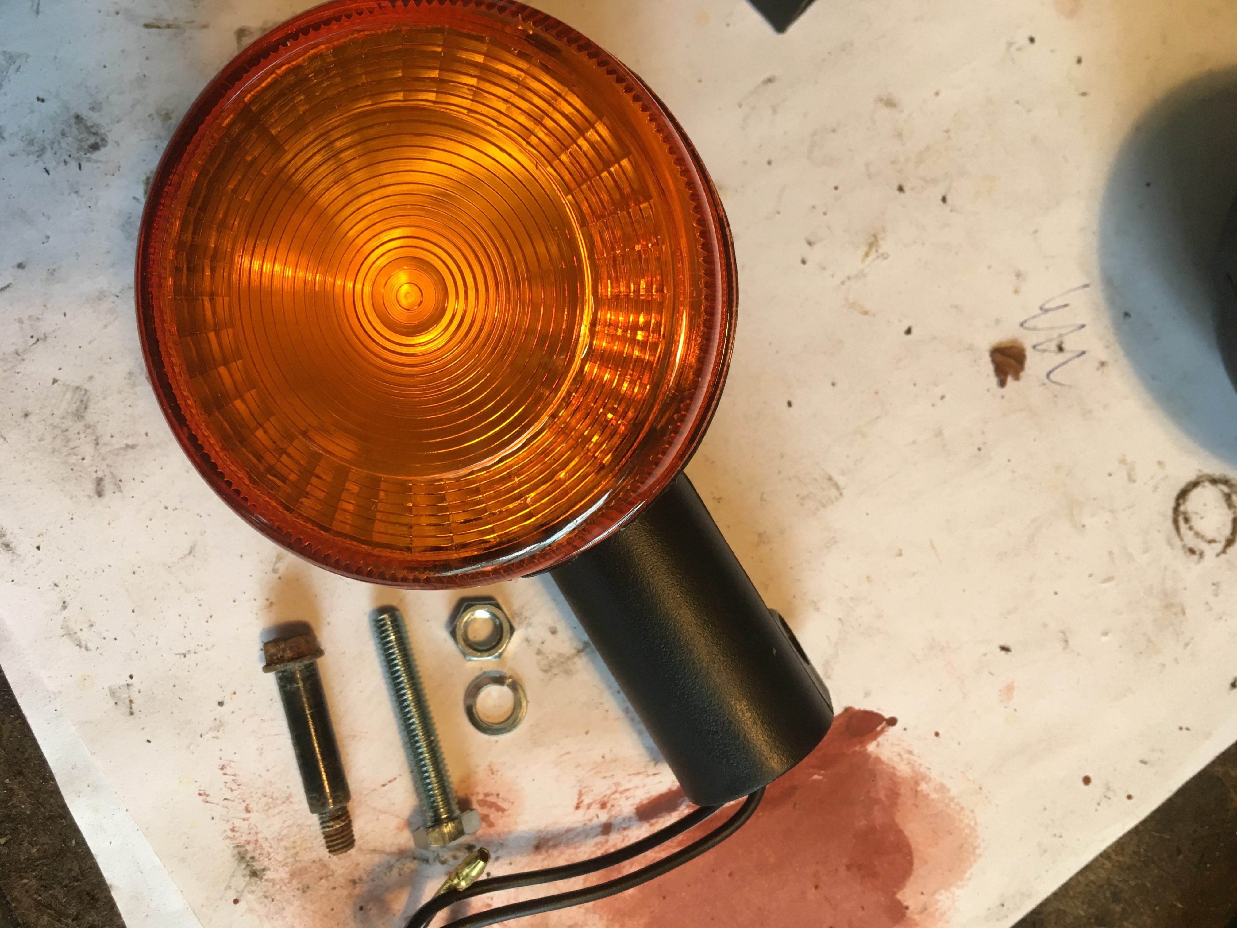
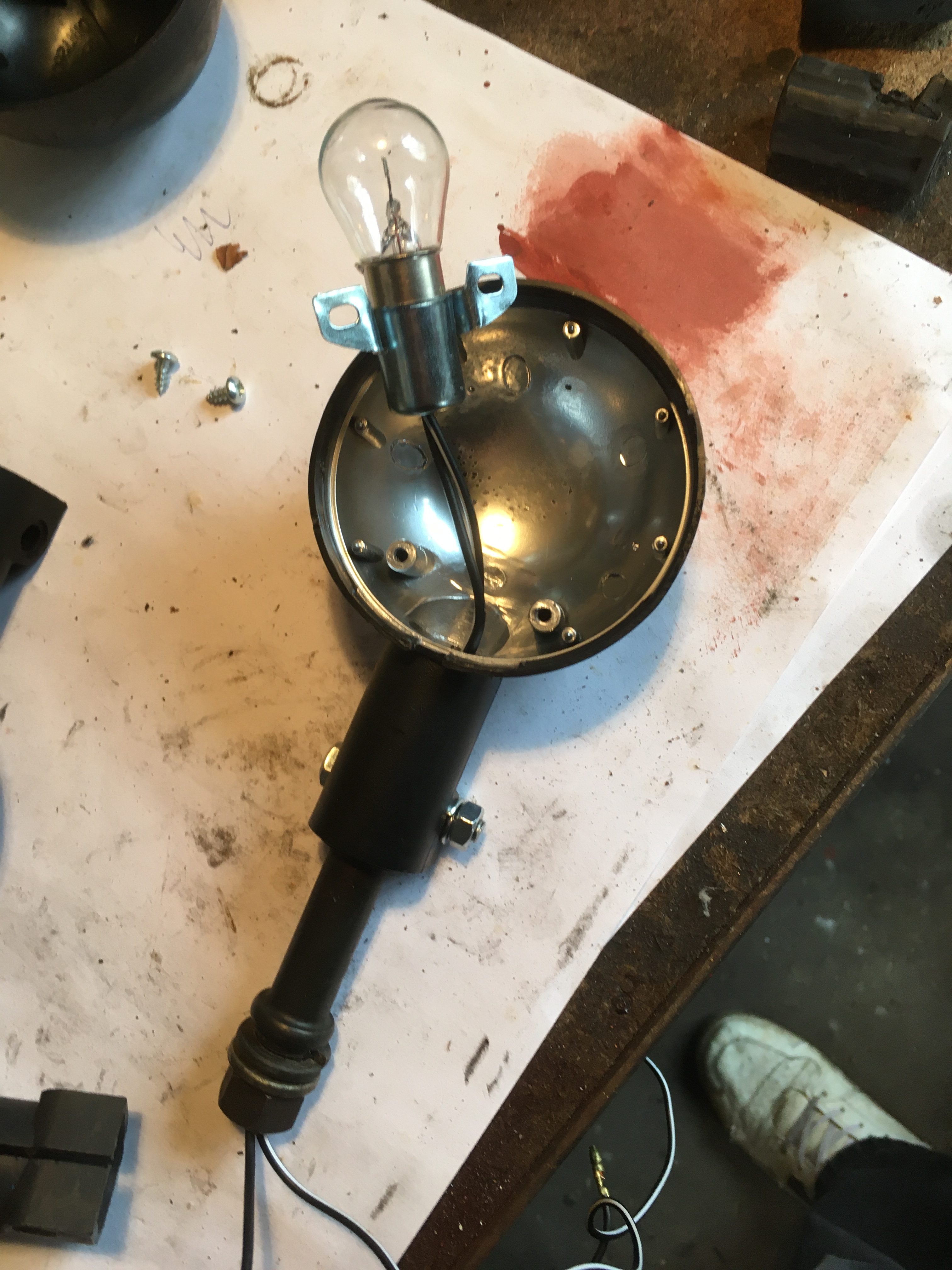
While tackling the switch-gear, I also cleaned, rewired and repaired the two original indicators I had in the parts box, ensuring the correct wire colours. these two were mounted on the rear of the bike, with the two new pattern indicators mounted on the front.
The pattern indicators are decent quality, but lack the Yamaha branding marks inside.
From the outside, the black plastic cases look identical to the OEM Yamaha ones.
The lenses are OK but again, lack the OEM markings having absolutely nothing embossed on them, let alone part numbers.
The interior is silver coloured, which is a nice touch, but again, not original, and of course the wiring is generic Black and Black/White rather than the Original colouring which would match the loom.
The supplied pinch bolt is nothing like the original Yamaha bolt.
A dab of common or garden engine oil served to ease the indicators onto the rubber stubs. It’s a tight fit!
The finished switches were mounted on the handlebars at the same time along with the new horn, bolted to its bracket behind the headlamp shell.
We’re nearly there now with most of the electricals mounted on the rolling chassis.
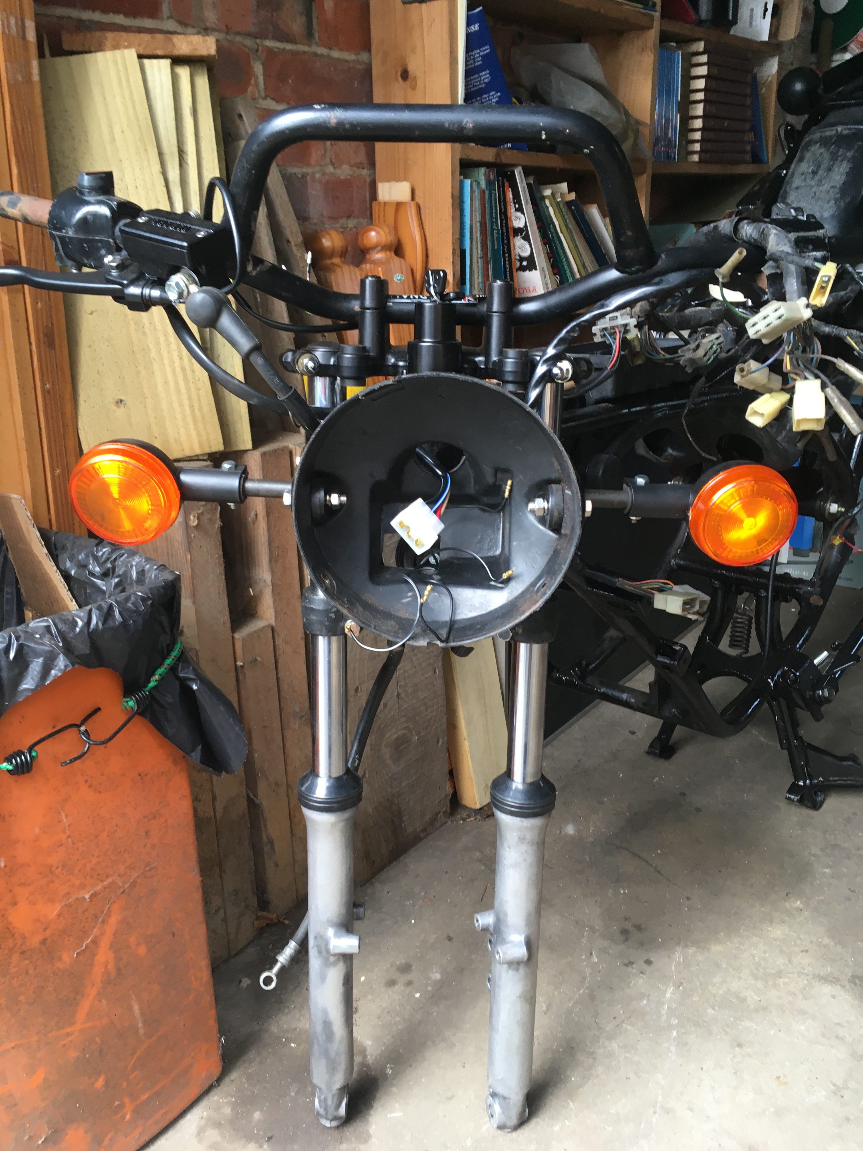
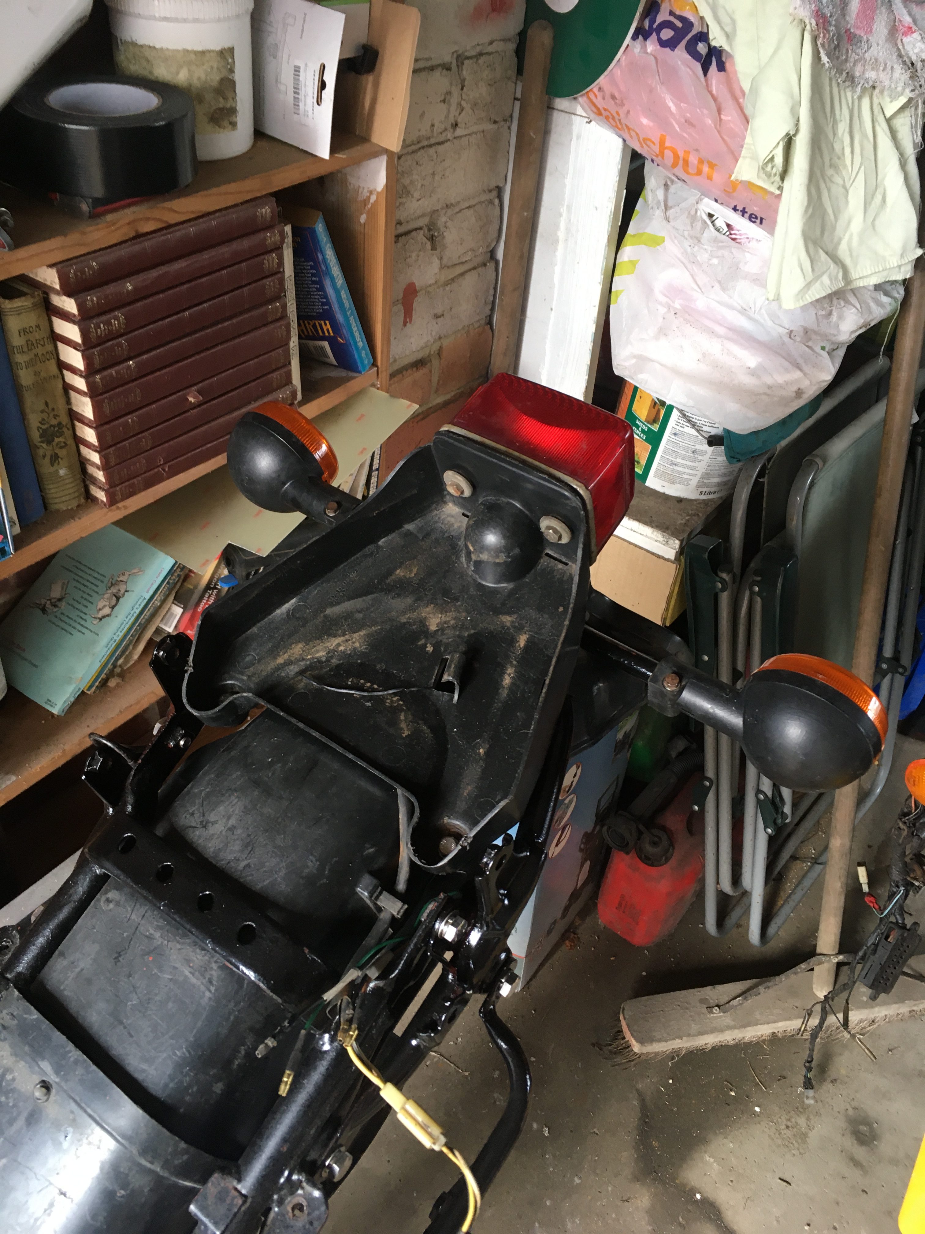
I have put the pattern indicators on the front, and the 2 decent original indicators I have on the back.
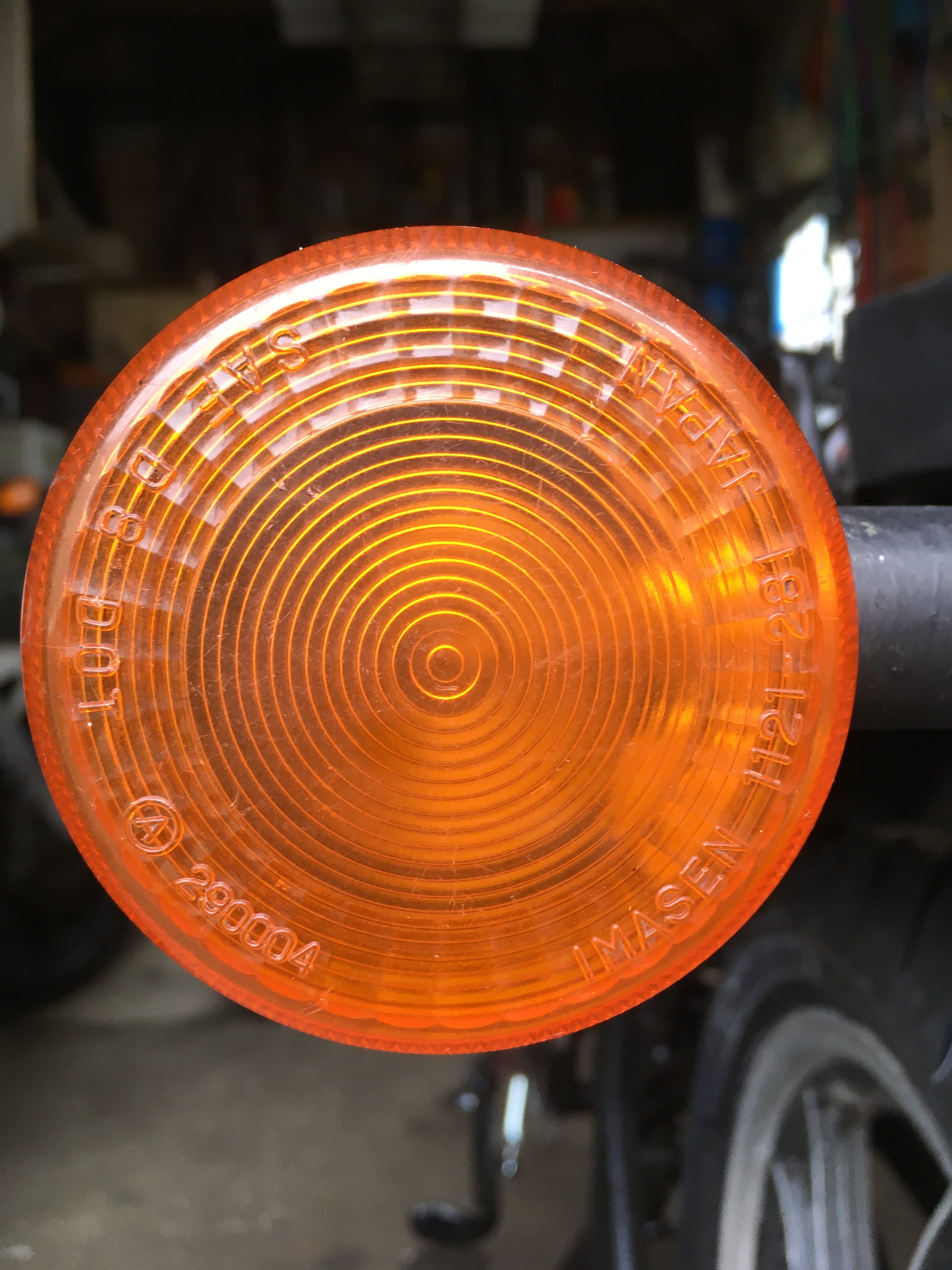
Interestingly, when the LC’s first hit the UK roads in 1980/81, the rear indicator lenses were different to the front ones, the rears being sort of opaque, while the fronts were more transparent.
this was reflected in the part numbers…
Front : 3Y68331200
Rear : 4L08333200
…and the markings on the lens itself
Front : 290005
Rear : 290004
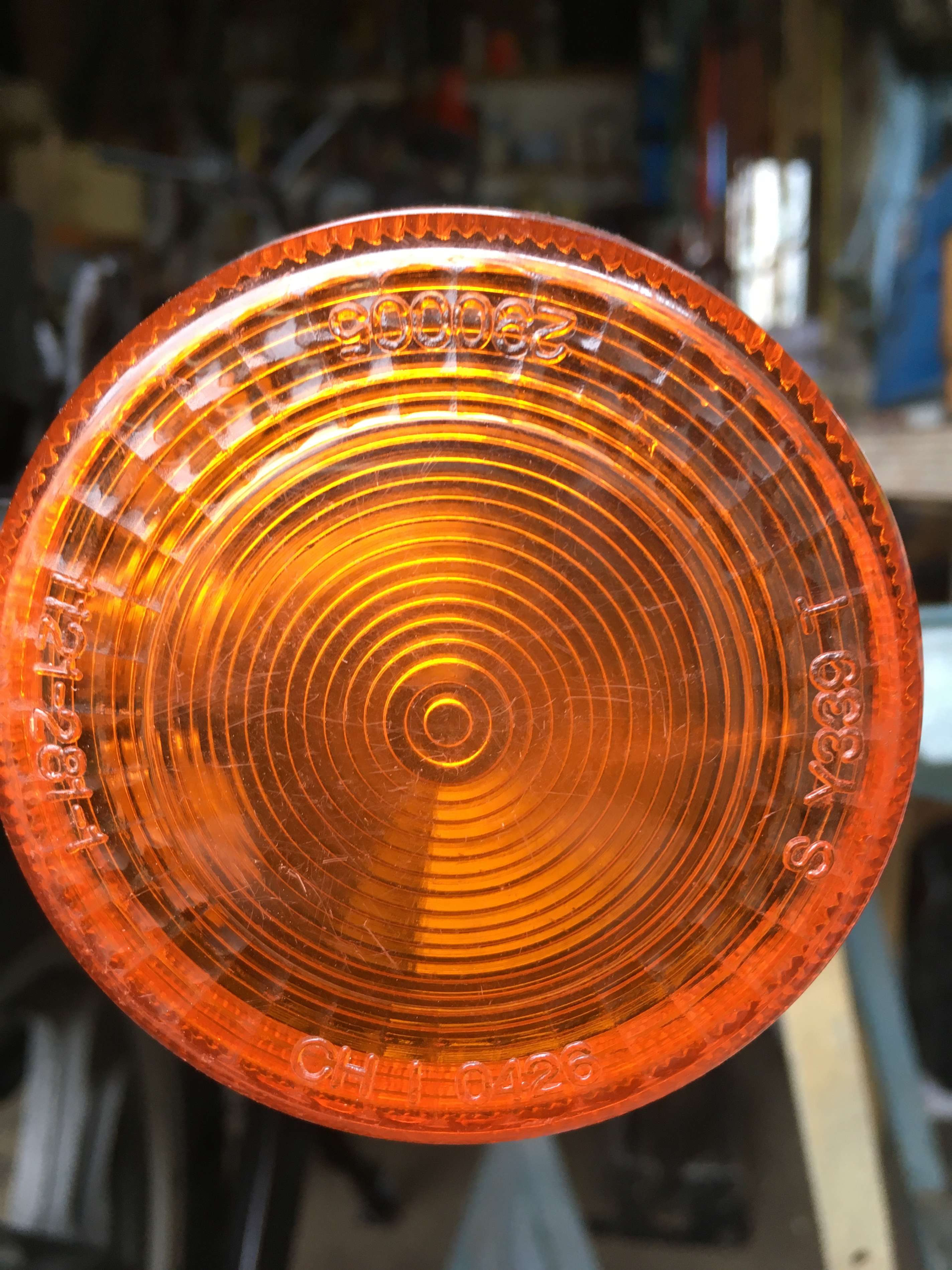
Front marked 290005 
Rear marked 290004
If I were performing a concourse build, (which I am absolutely not!), it’s a detail I’d like to get right.
Sometime in the mid 1980’s, it appears that Yamaha dropped the different rears from their parts catalogue, and specified the transparent lenses for all 4 corners.