Crank and joining the cases.
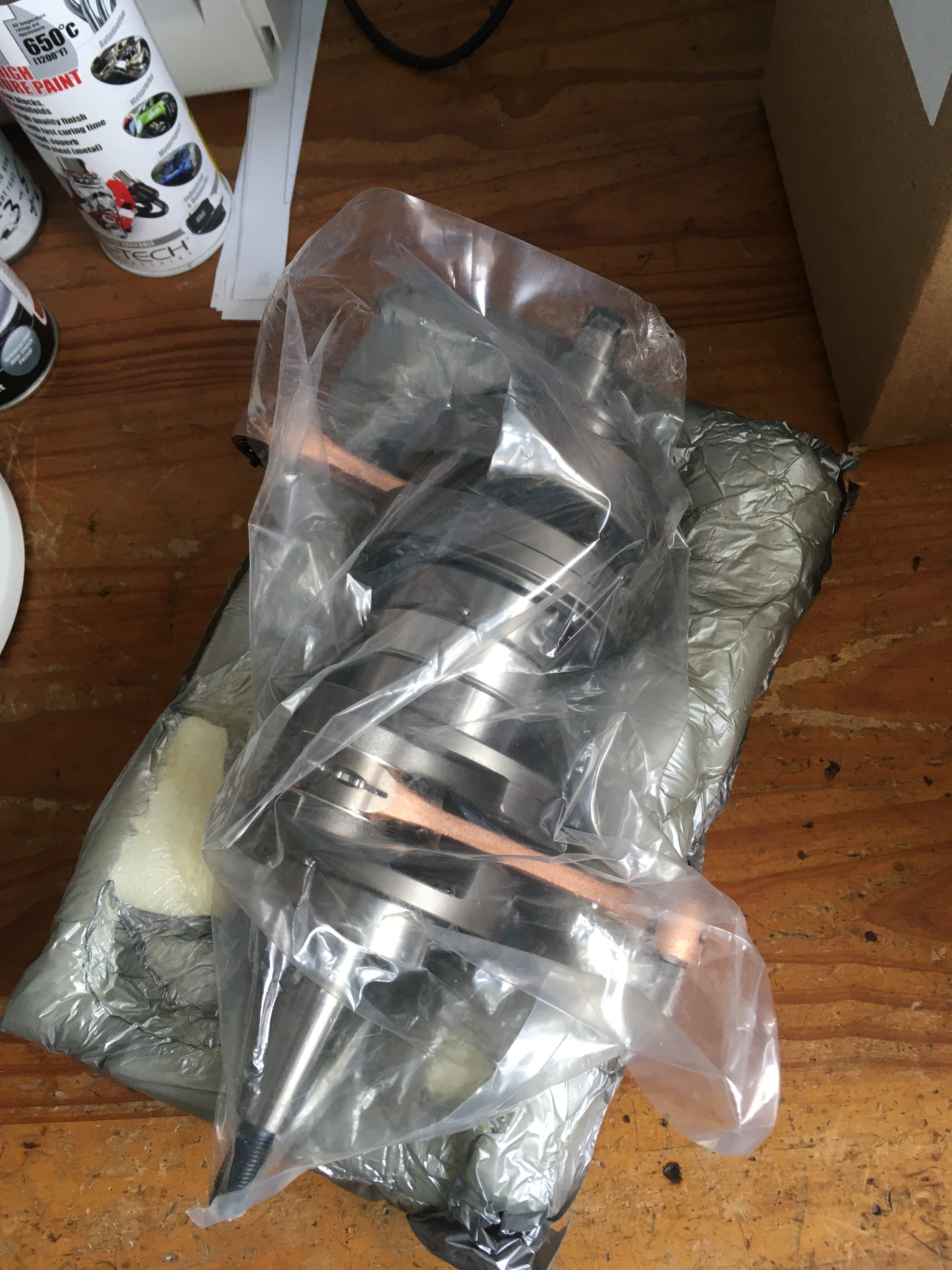
The new crankshaft arrived in the post from RDLCCrazy today. it’s time to press on!
I found all of the relevant cable routing clips for the top bolts hidden away in my parts box.
it must be the first time in three decades that the engine has had it’s full complement of clips.
Common wisdom is to grease the lips of the oil seals, so that was done in addition to putting some engine oil on the crankshaft ends.
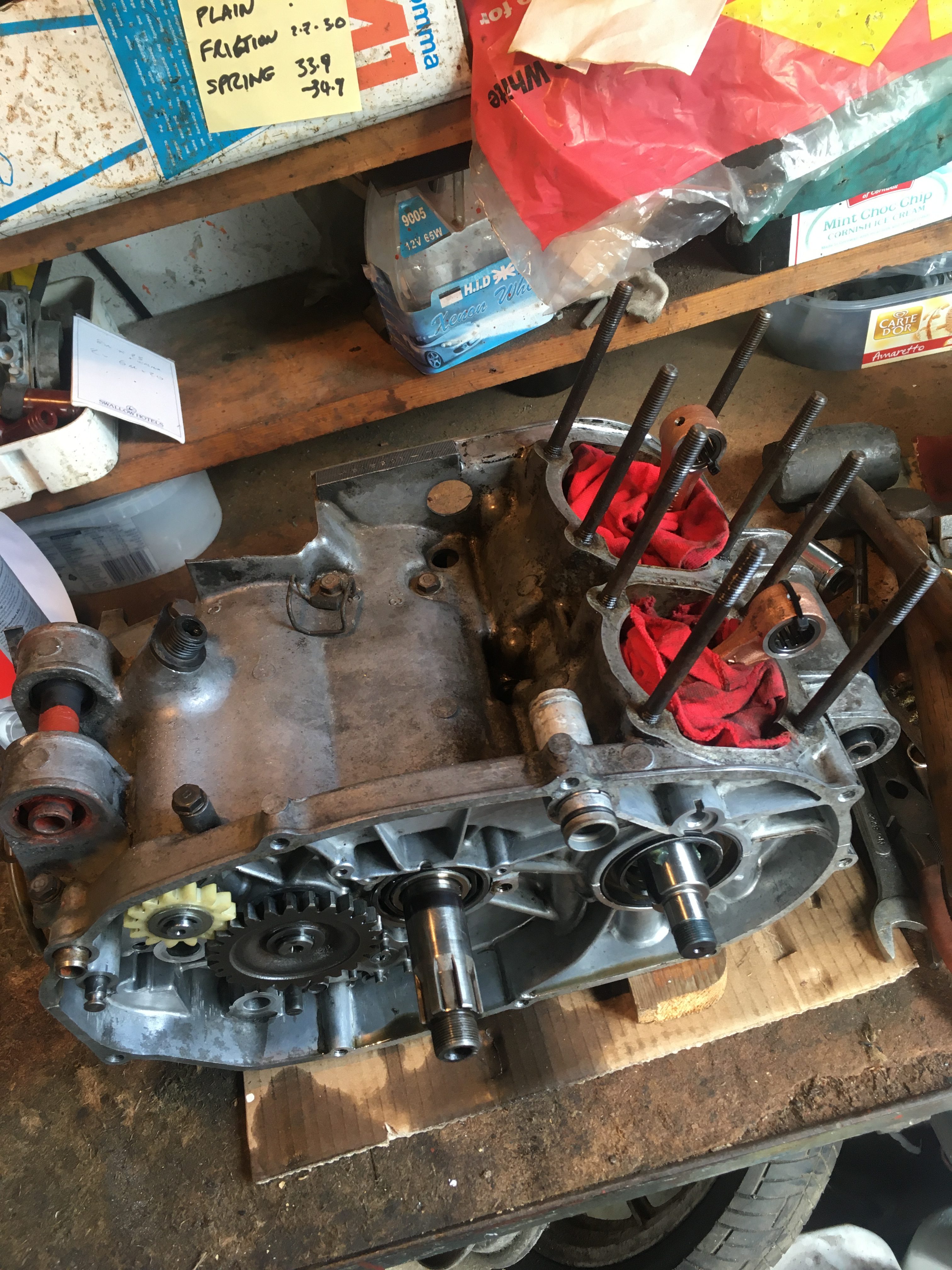
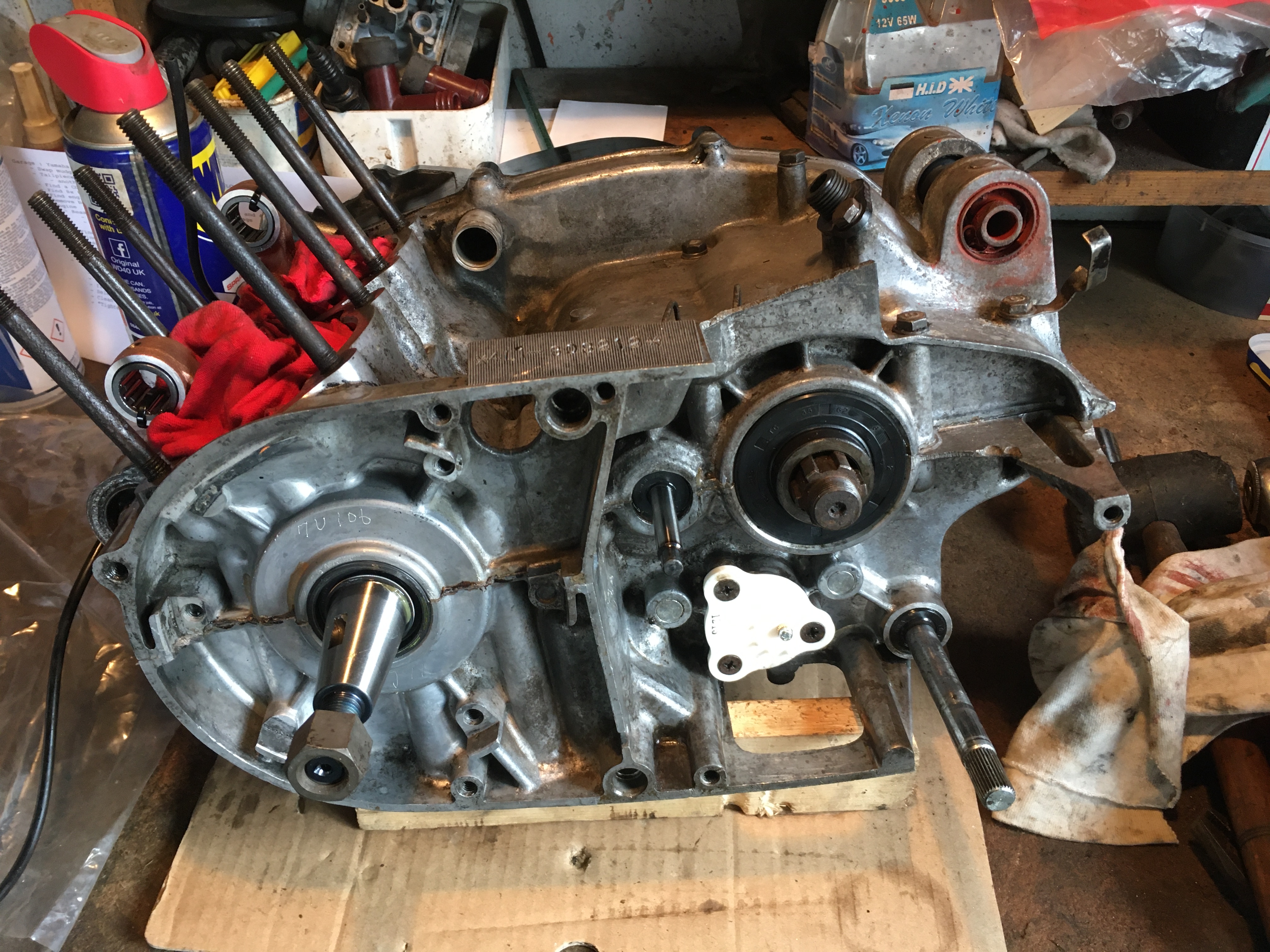
The crank center labyrinth seal was an exceedingly tight fit into the bottom crankcase half, which meant that the crank rocked side to side a little.
After fitting the crankshaft oil seals, I persuaded the crank to lie flat with some gentle help from a block of wood and a rubber mallet on the center bearings.
After making sure all of the bearing locator pegs were in position in their slots, I smeared the tip crankcase half with some clear silicon gasket cement, and brought the two halves together.
Now I have reached this stage, I’m wishing I had sent the cases off for vapour blasting… but they are clean enough and frankly, the rebuild bill is growing way past the initial projections!
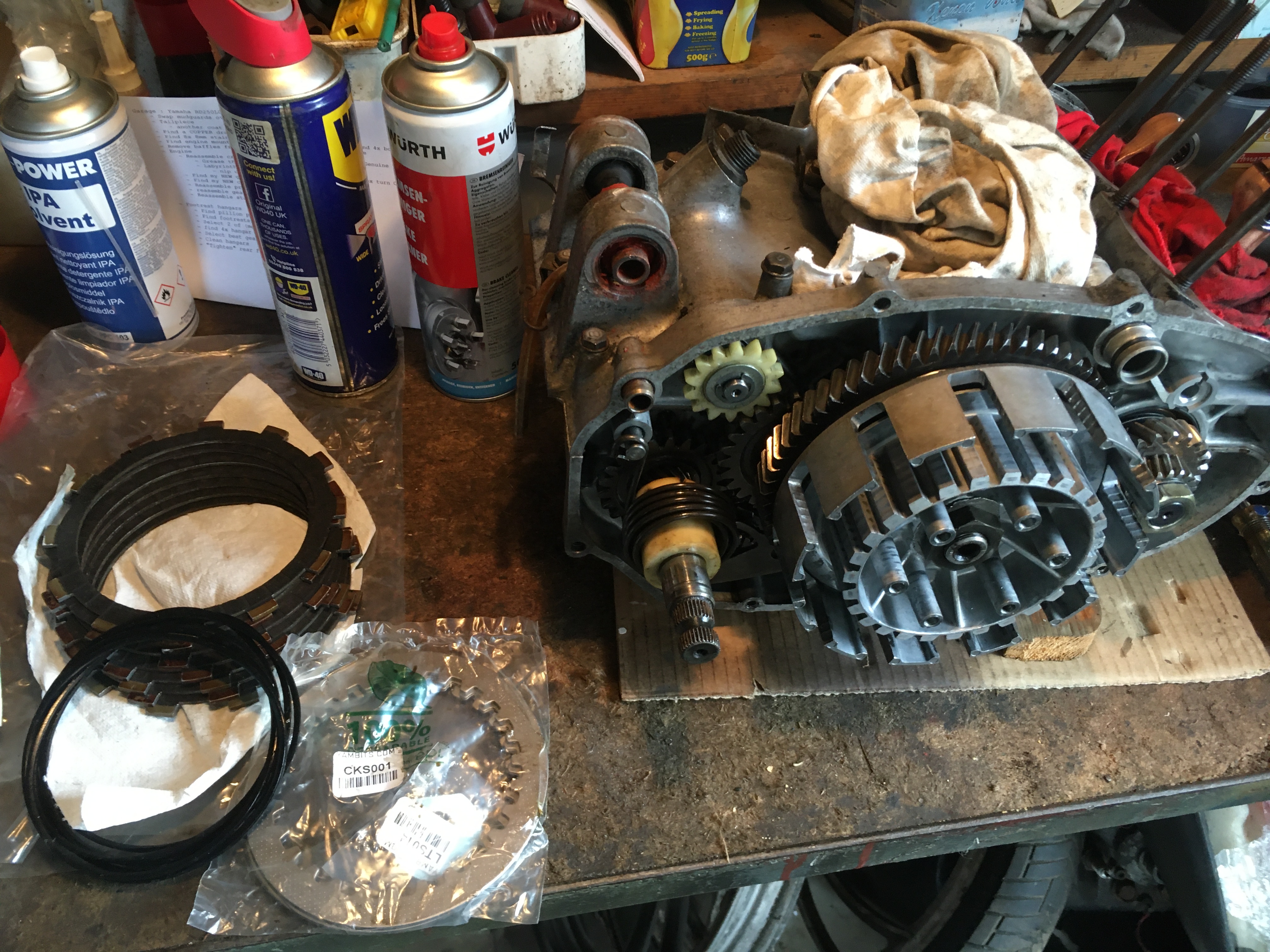
Clutch and Primary gears
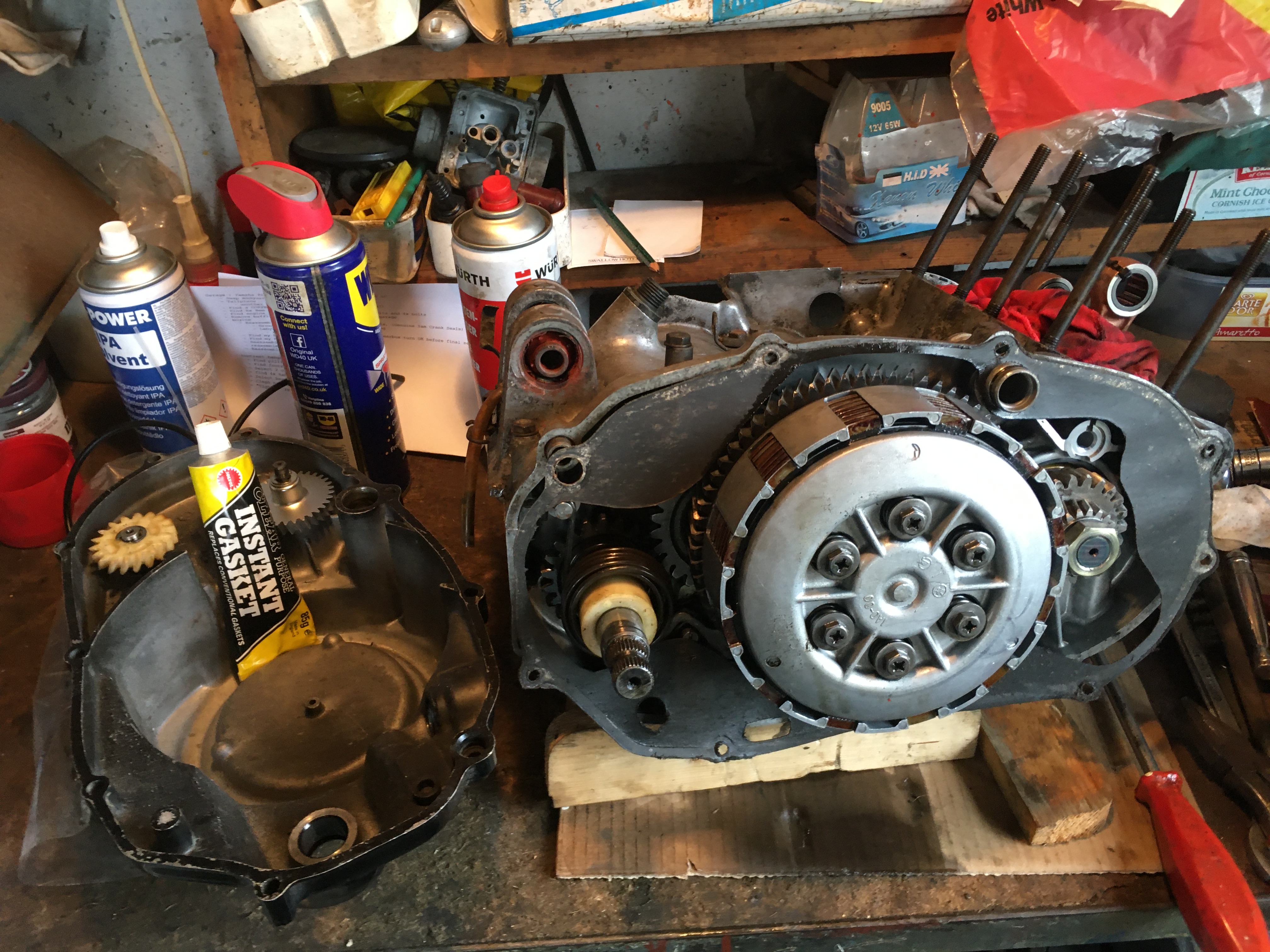
When I took it apart, I noticed that the primary drive gear had a number scribed on it. A little research eventually turned up the fact that the Primary drive pinion, and the clutch basket drive are matched at the factory. the numbers scribed on both parts should add up to 155 +/- 1 to optimise the clutch drive gear mesh and reduce drivetrain backlash.
My numbers were 61 on the clutch basket and 81 on the primary drive pinion… adding up to 142, woefully short of optimal.
A pass through my box of spares turned up 3 other primary drive pinions, one with 91 scribed on it, giving me a total of 152, which is the closest I can get with what I have.
So the 91 pinion was the one installed on the end of the crank.
New plain clutch plates were used as the donor bike ones had corroded, but the friction plates appeared OK and measured well within the wear limit specified, so were re-used after a thorough clean with brake cleaner, and then a soak in gearbox oil.
The original gasket was in fair condition, so was reused with my favoured clear gasket goo.
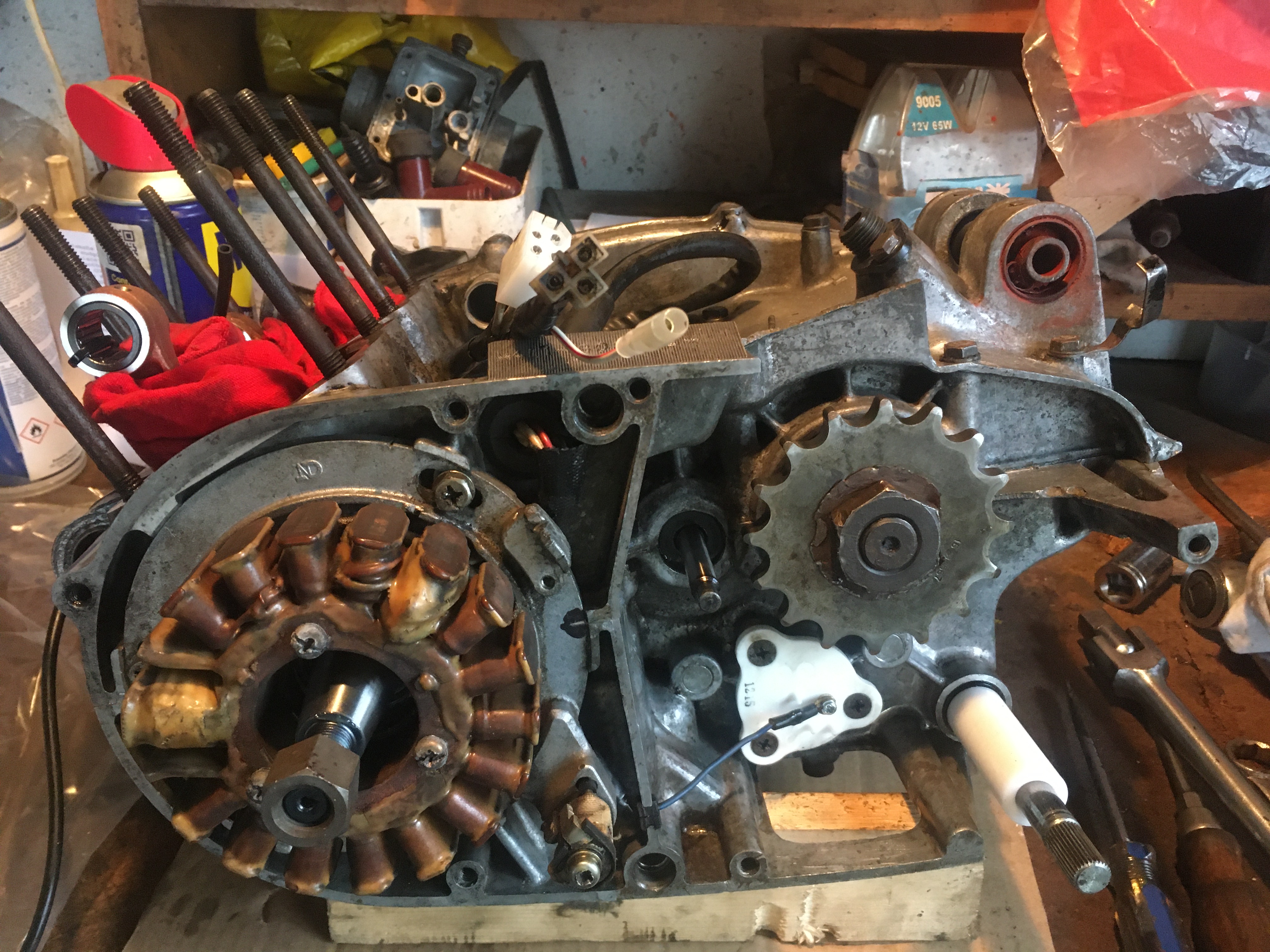
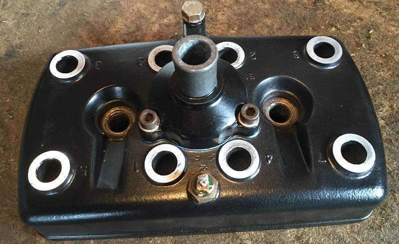
Timing plate and rotor
The timing stator went back on lining up the mark I made when dismantling with the case join. this gets me “close enough”, and with standard untuned engines, I have deemed this to be sufficient in the past, but best practice… and what I’ll be doing this time is a proper timing measurement using a dial test indicator to determine top dead center.
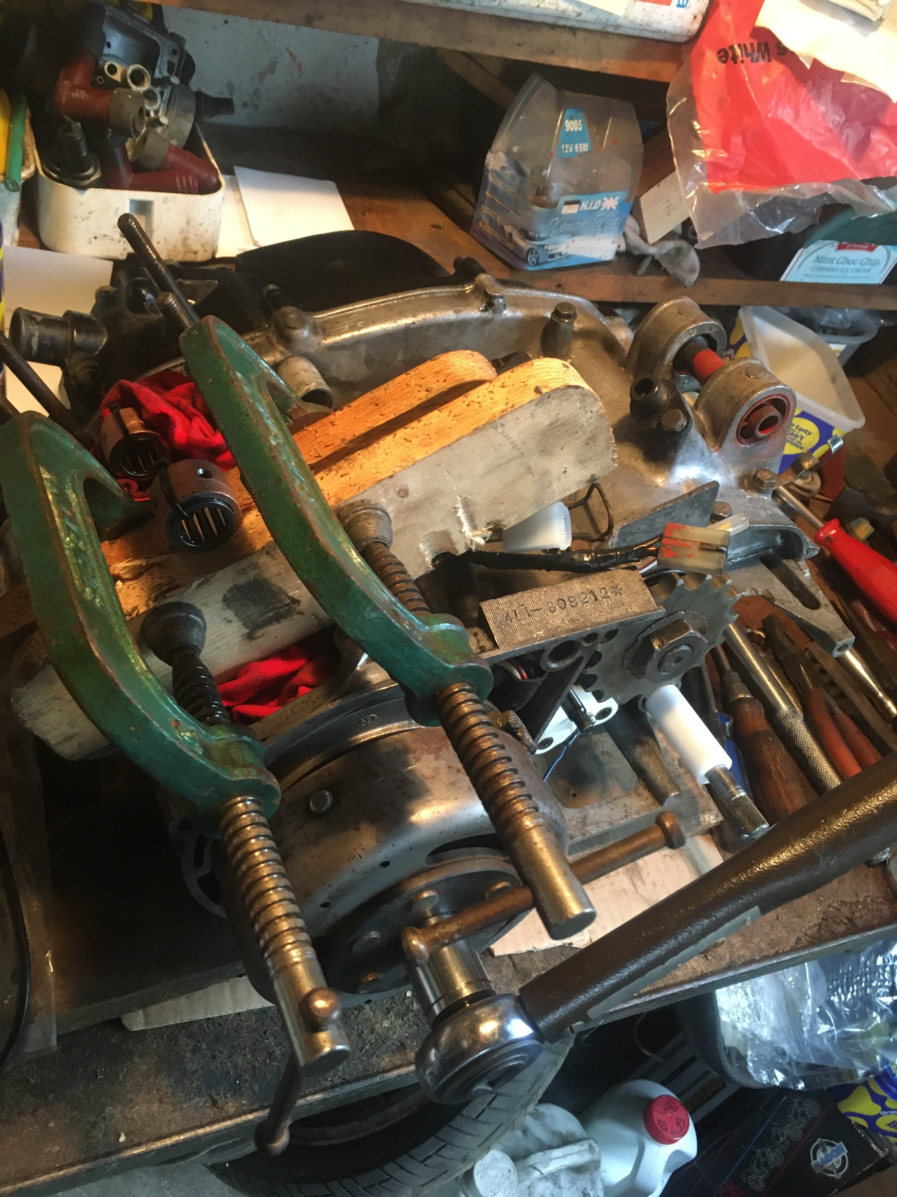
The rotor went back on with no fuss, and the odd arrangement of nuts which were on the end of the crank are now replaced with an actual LC crank end nut, plain and spring washers.
I have no special tools, so the nut was tightened to the correct torque setting by clamping the con-rod with the Heath Robinson affair pictured.
Now it is time to look at the top end, with a view to fitting.
i have three 250 top ends to choose from, and all show a degree of wear.
I selected one pair of barrels because it had a pair of matching pistons with it. The other top ends I have either are missing pistons or the pistons are damaged.
These were the barrels I invested time and effort in cleaning and painting.
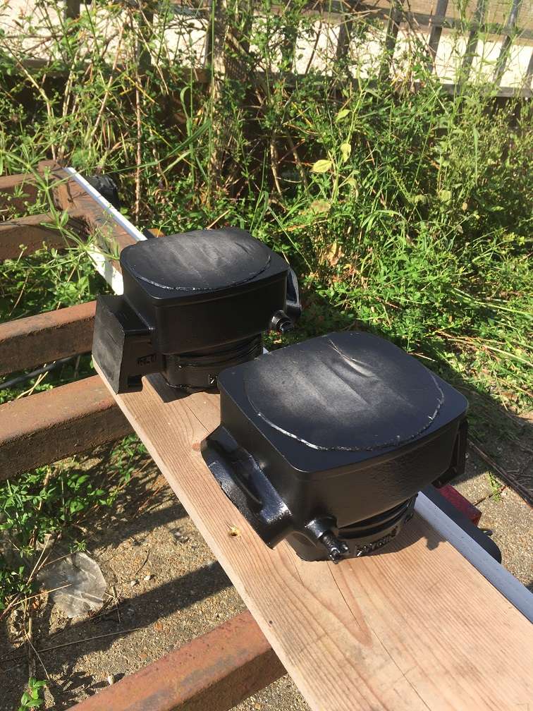
Removing the pistons from the bores, and giving everything a thorough clean showed that what had appeared to be some minor scratching turned out to be major scoring.
In addition, there was a pronounced “lip” at the top of the barrels above where the piston rings sweep to.
I don’t have an internal micrometer, so cannot accurately measure the bores.
The pistons measured 54.5mm at the bottom of the skirt, exactly what would be expected given the 0.50 oversize stated on the top of the piston.
But they seemed baggy in the bores, so I decided to do a ring gap measurement.
That is, removing the top ring from a piston, placing it in the top of the bore, and gently pressing it down the bore about 2.5 cm with the base of the piston.
this places the ring at the maximum wear point in the bore, and ensures it is square.
The gap between the ends of the ring can now be measured with a feeler gauge, and should be in the range 0.3mm and 0.45mm. i.e. Less than a half millimetre.
my gap was visibly greater than that, and when measured, amounted to 3.5mm.
This amount of wear, plus the scoring in one cylinder bore convinced me that I had to invest in a rebore and new pistons, so i packed them up, and off they went to PJME.
With a 2 week turnaround, we have some more “Meanwhile” blog posts coming up, where I tackle some of the other project jobs while awaiting parts to continue the engine build.