After the brief interlude of building (yet another) 350LC, so I could register the acquired NOVA frame, it’s back to the refurb of my original RD350LC.
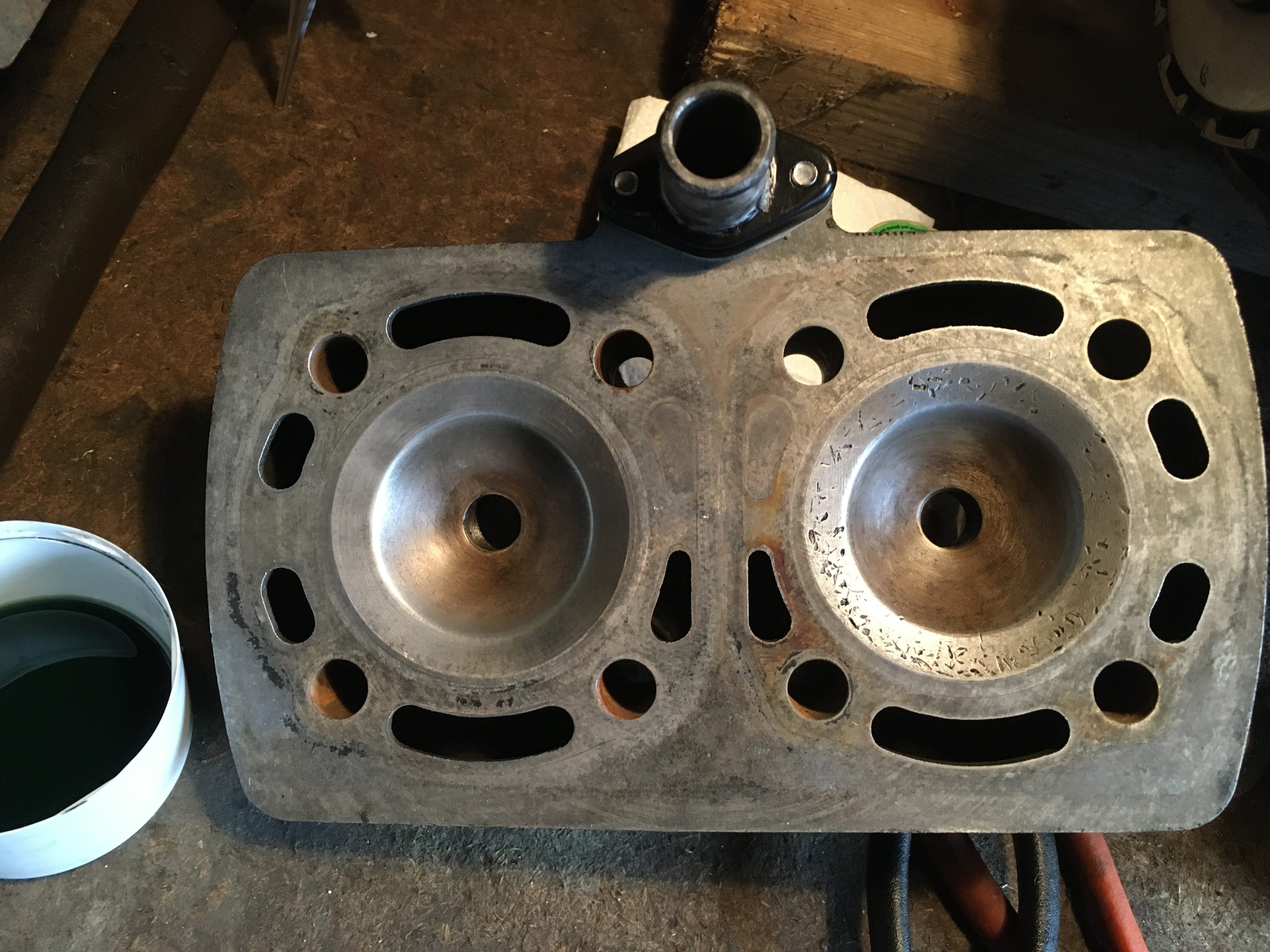
I’m using the original barrels and head I had fitted to the bike when it covered a reliable 10,000 miles. these will be fitted onto a “spare” bottom end I have, which only has 3000 miles on the crankshaft.
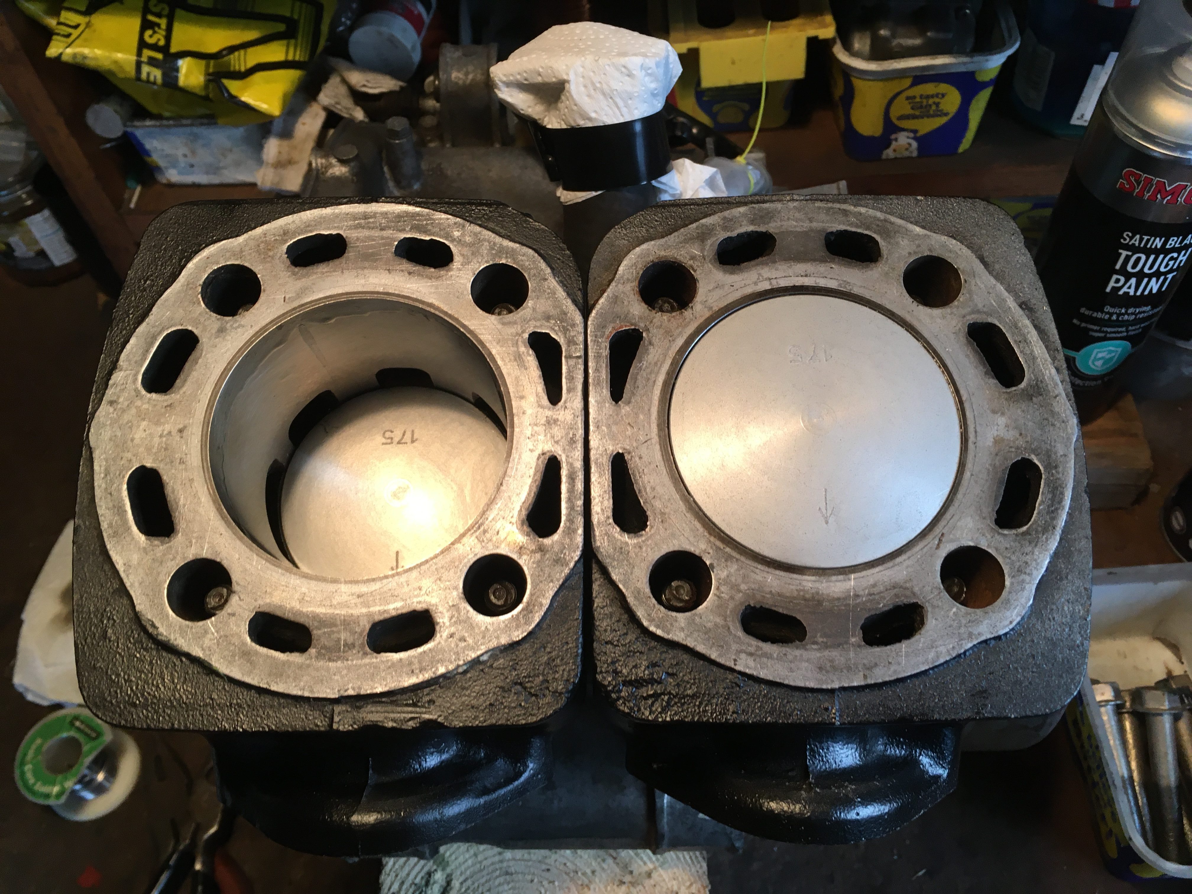
The barrels have been rebored to 1.75 O/S by PJME.
They have been tuned a bit by Bob Farnham, many years ago, when I had intended to enter the LC into an 8 hour endurance race. We ended up using a Honda CBR600 instead, which spared my LC, and that tuned engine spent many years on the road, being fully reliable.
I do want to know what the squish and CR is though, so todays job is to measure it.
The squish on a standard engine from Yamaha is circa 2mm, and doesn’t follow the crown profile of the piston. This would be “safe” for spotty youths running on 2 star petrol, parafin, white spirit, or other.
The standard “trapped” compression ratio, measured from exhaust port closing, to Top Dead Center was 6.2:1 when supplied by Yamaha.
From my days racing a Suzuki X7, my aim for that pampered engine were a squish of 0.8mm, and a CR of around 8:1.
For my road going RD350LC, I would be aiming to ease off on those figures a bit.
Squish should be measured first, so that any adjustments to deck height, (by altering base gaskets and head gaskets, can be made before measuring the CR.
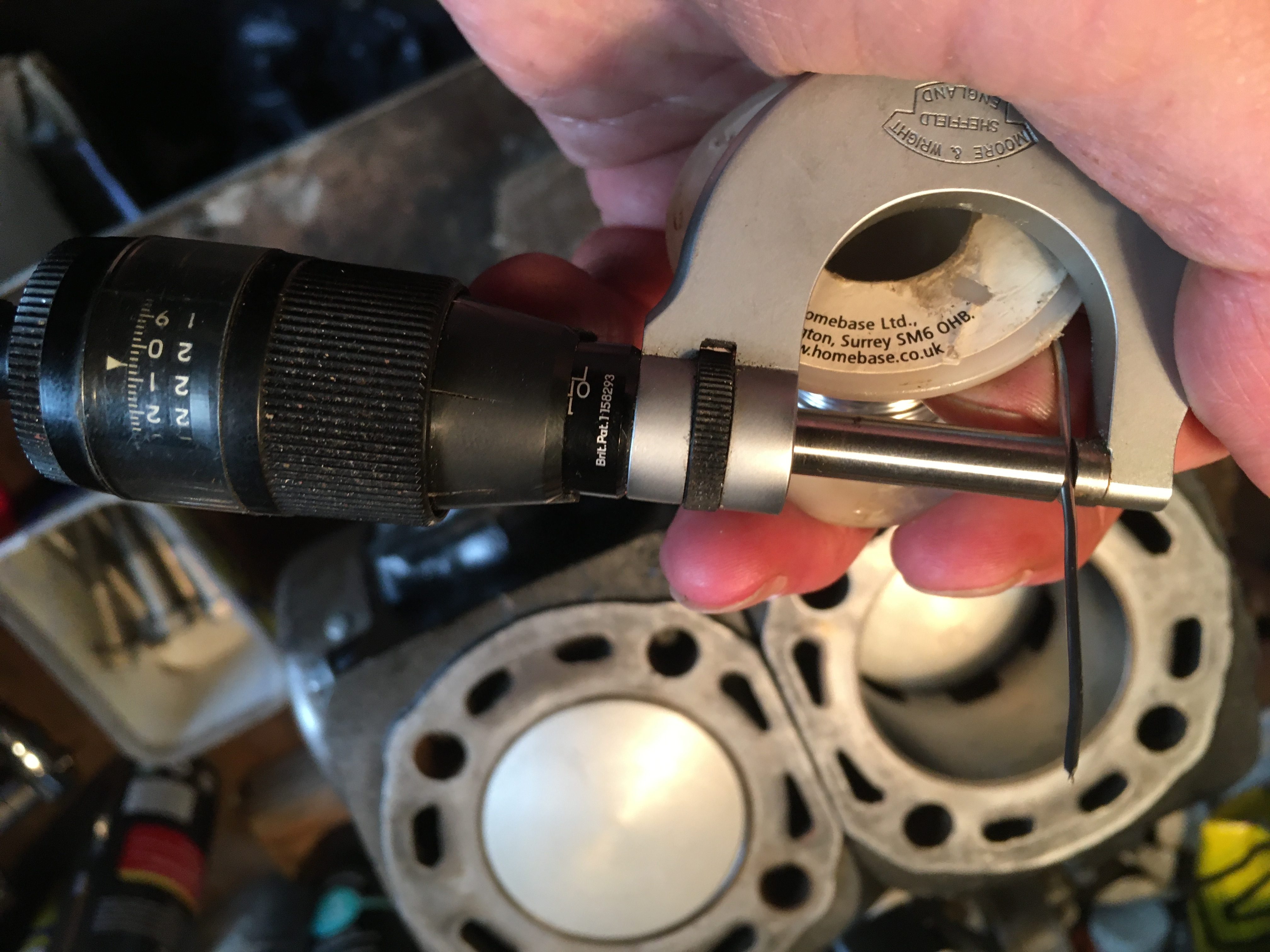
The squish can be measured by using soft electricians solder between the piston crown and the head, turning the engine over, and then measuring how much the solder has deformed.
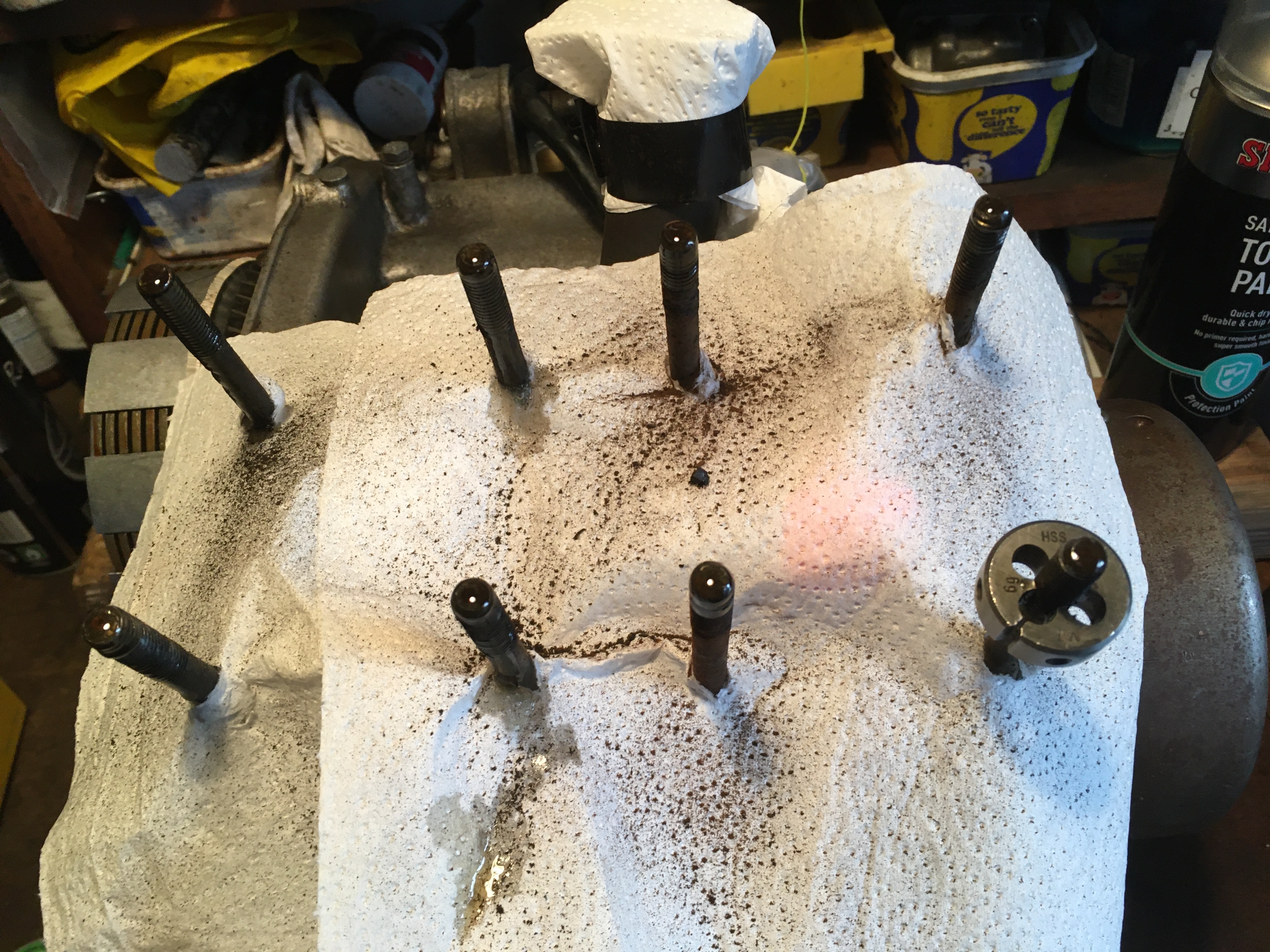
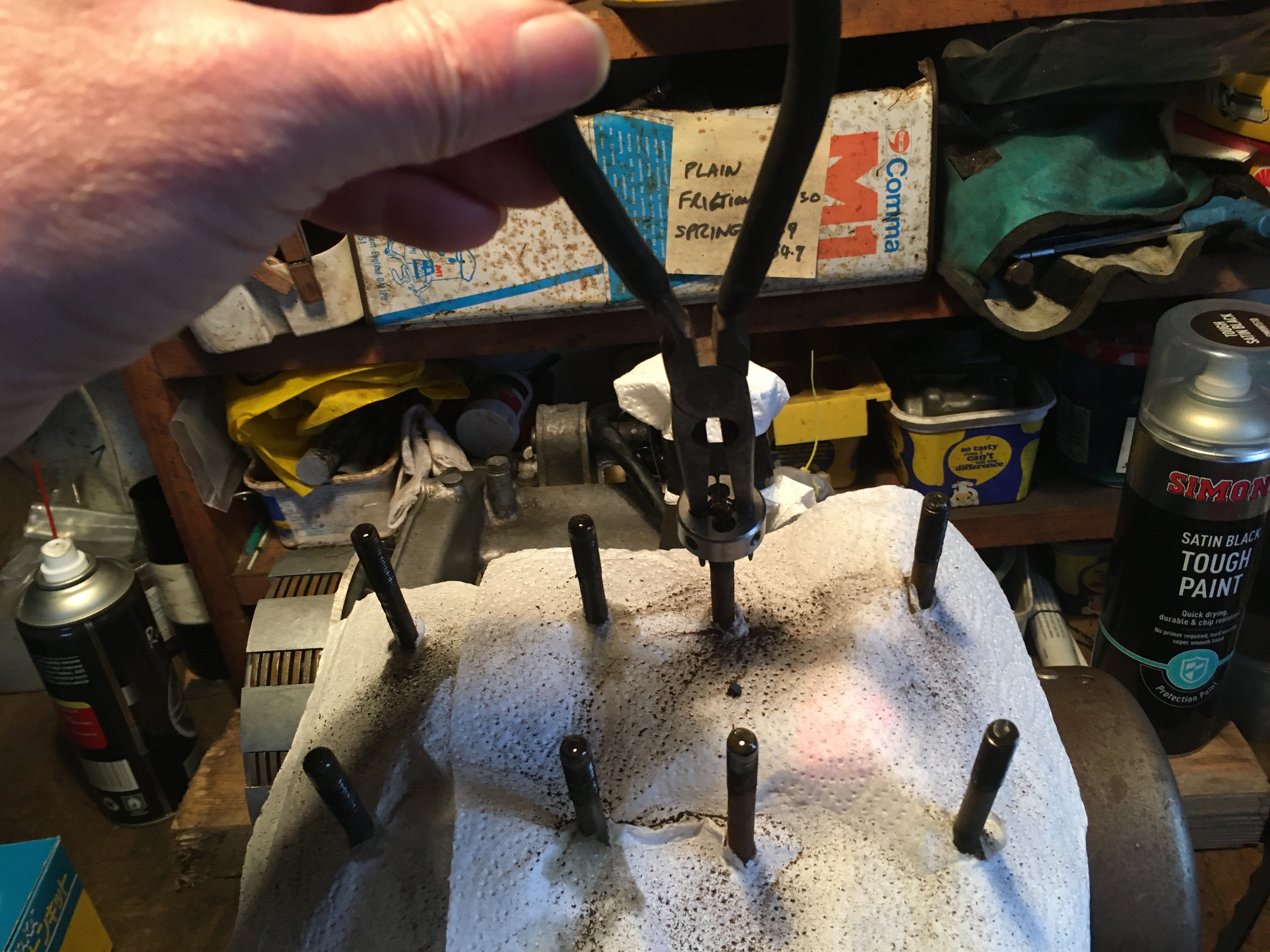
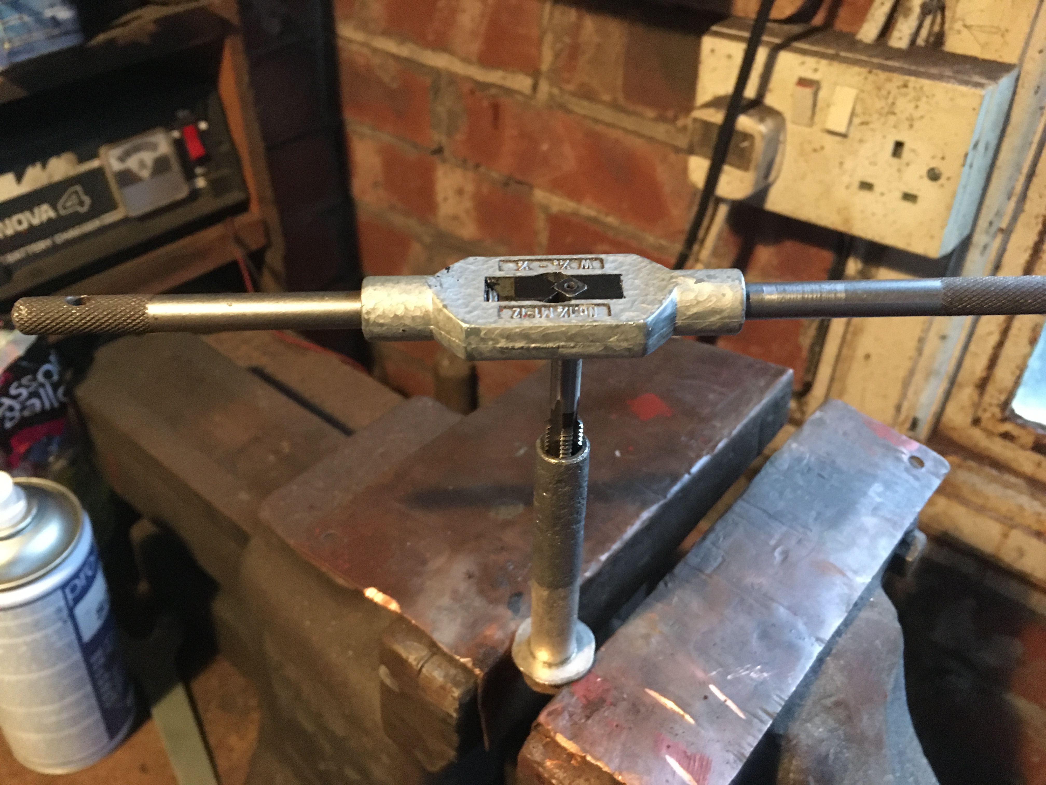
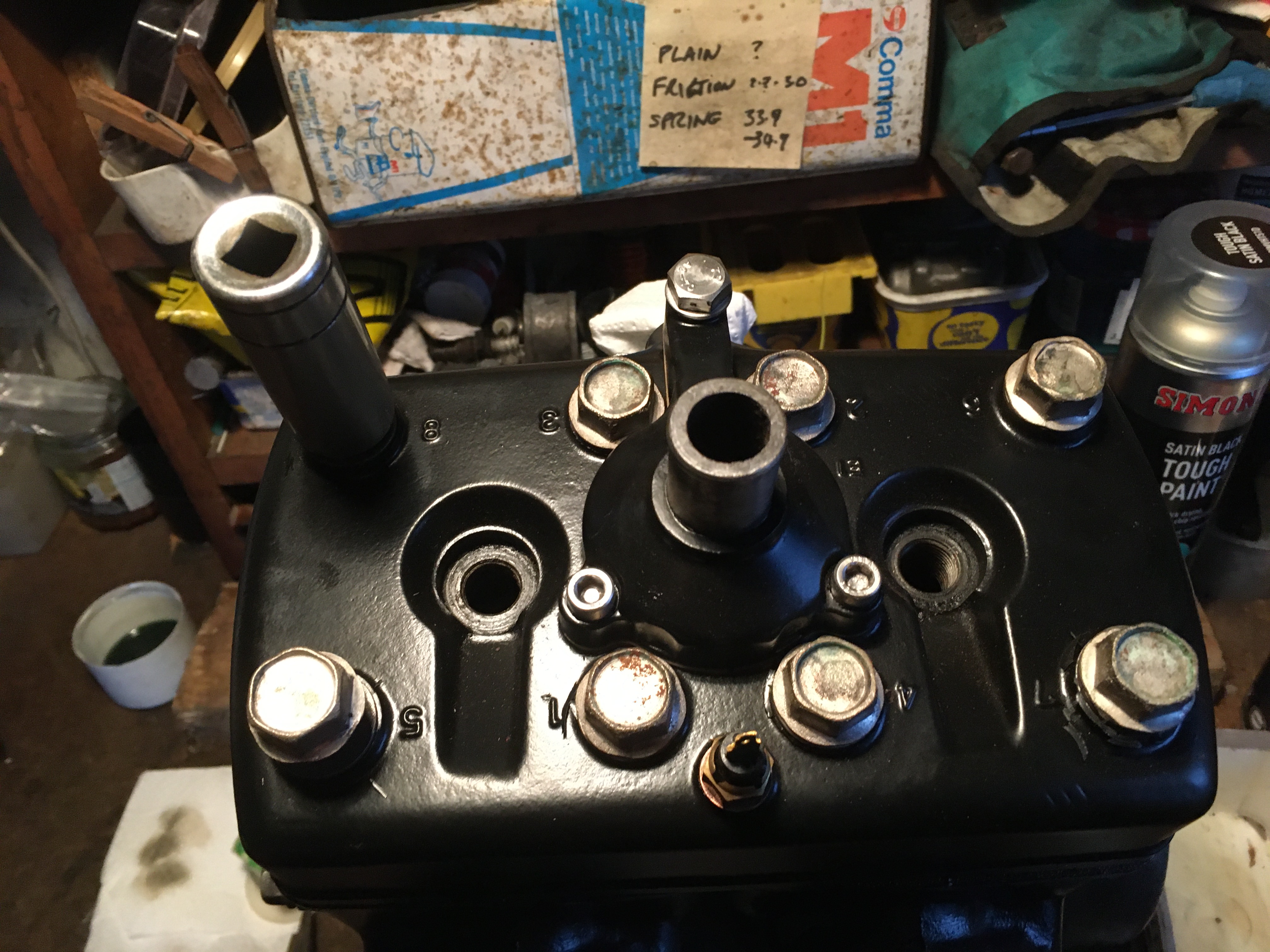
Retrieving the bottom end from under the workbench revealed that some remedial work in the studs was needed, so it’s an hour with the taps and dies to ensure all the bolts fit and turn by hand.
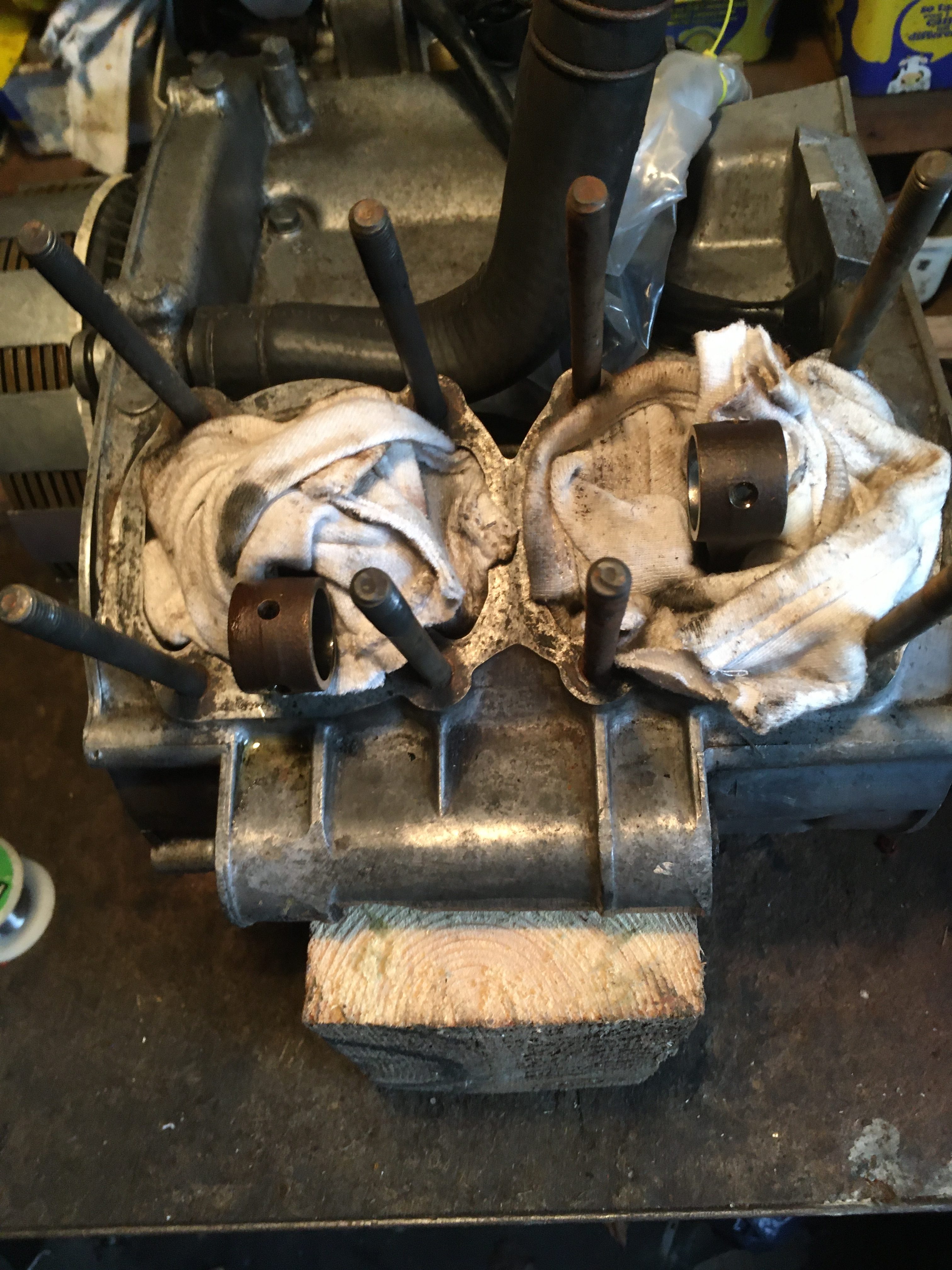
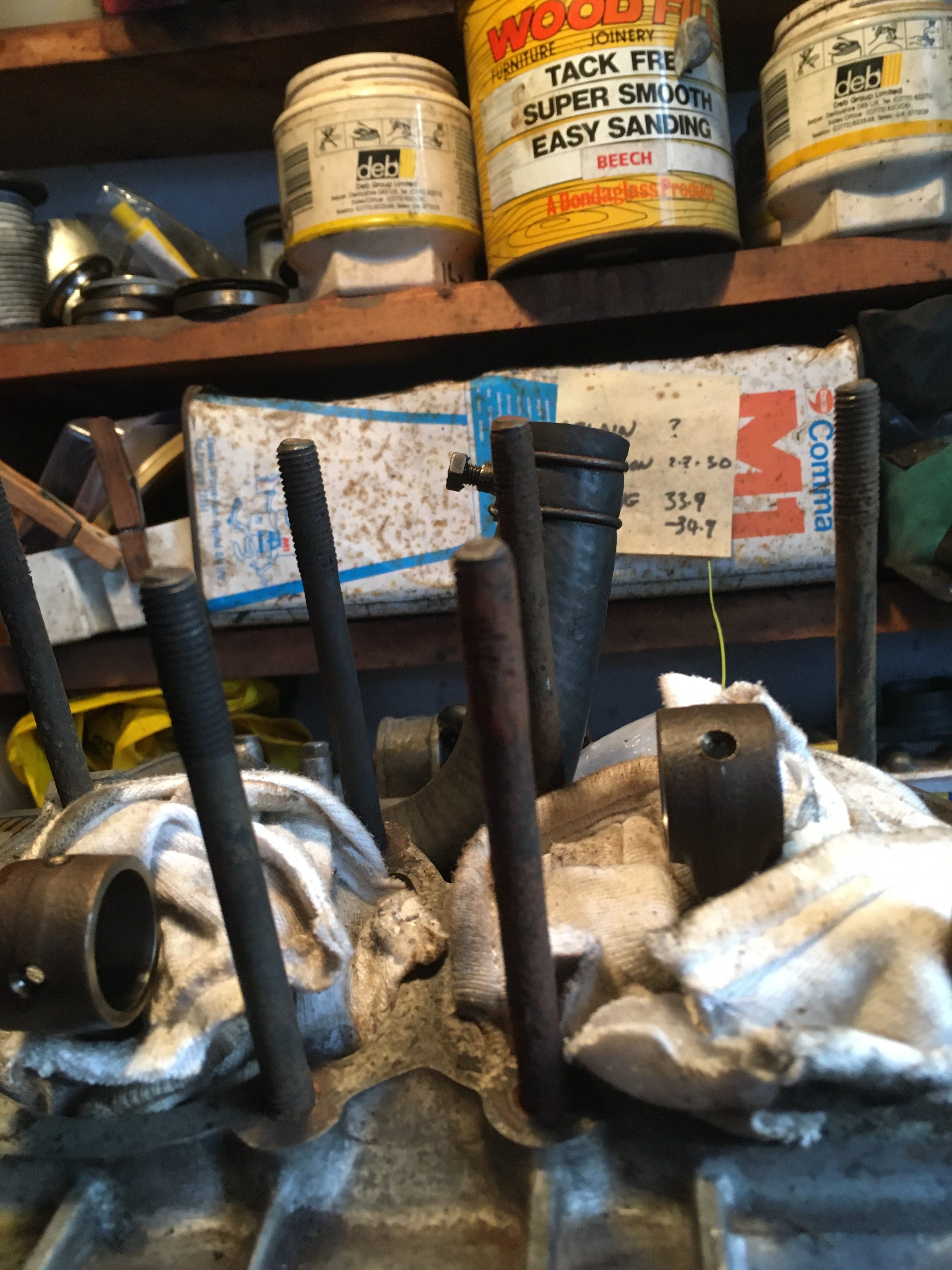
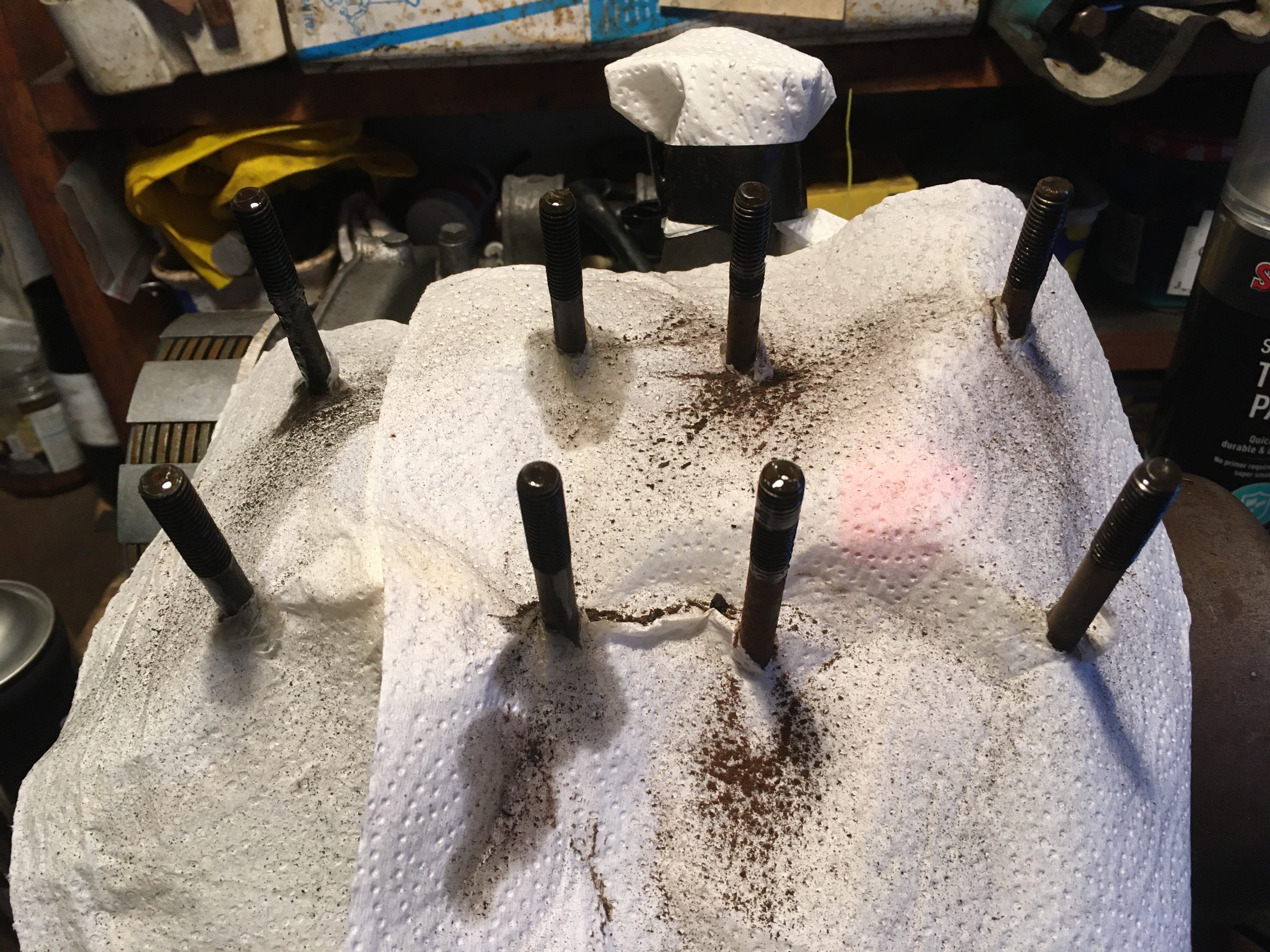
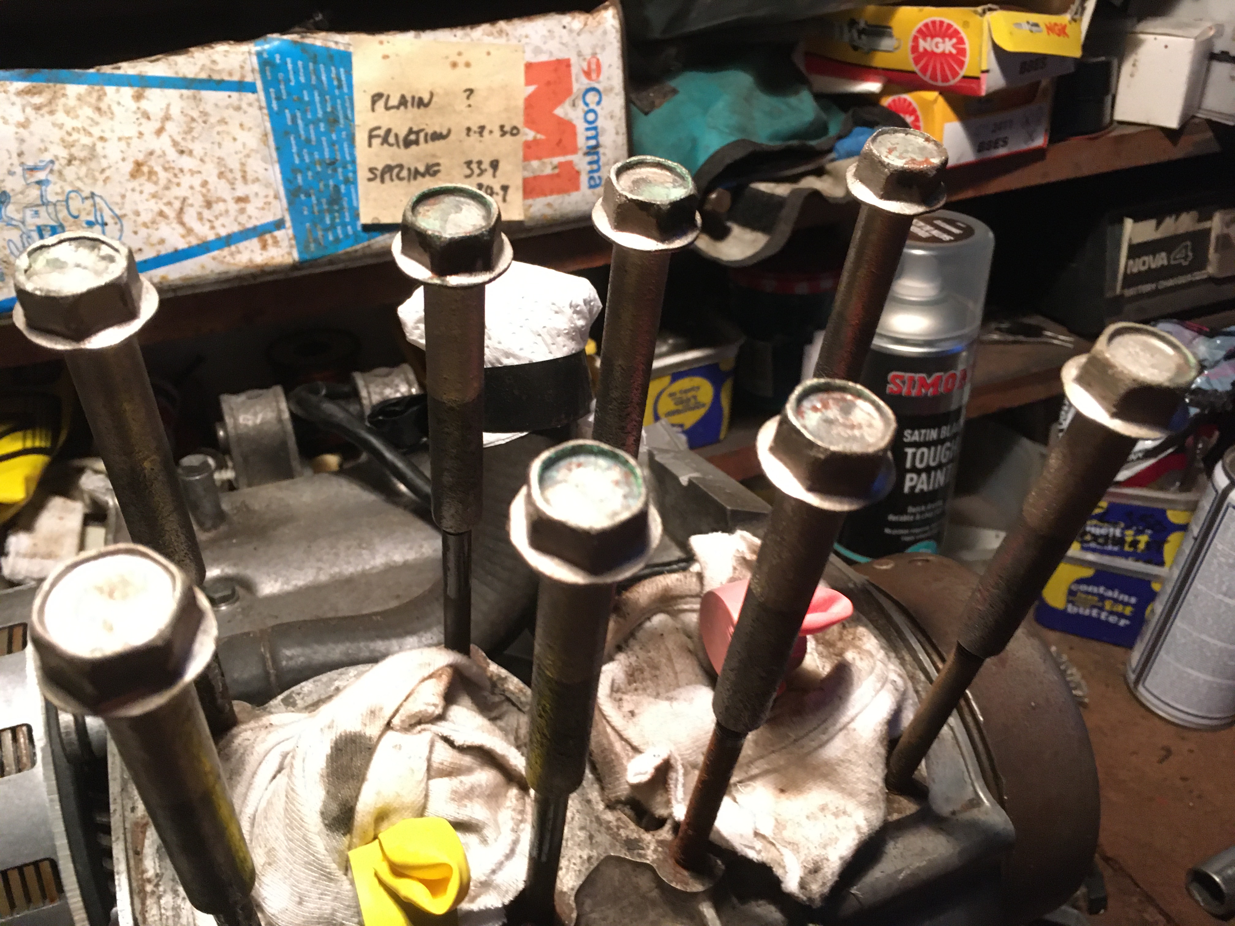
Now I can fit the new pistons and put the barrels on.
when the engine was built up before, it had “standard” base gaskets, but these can vary in thickness from 0.5mm to 0.6mm depending on where sourced, and who manufactured them.
I have a good used pair of pre-used base gaskets which measure 0,51 and 0.54mm, so I’ll use these.
I’m also using a pre-used head gasket which has the advantage of being already compressed to operating thickness.
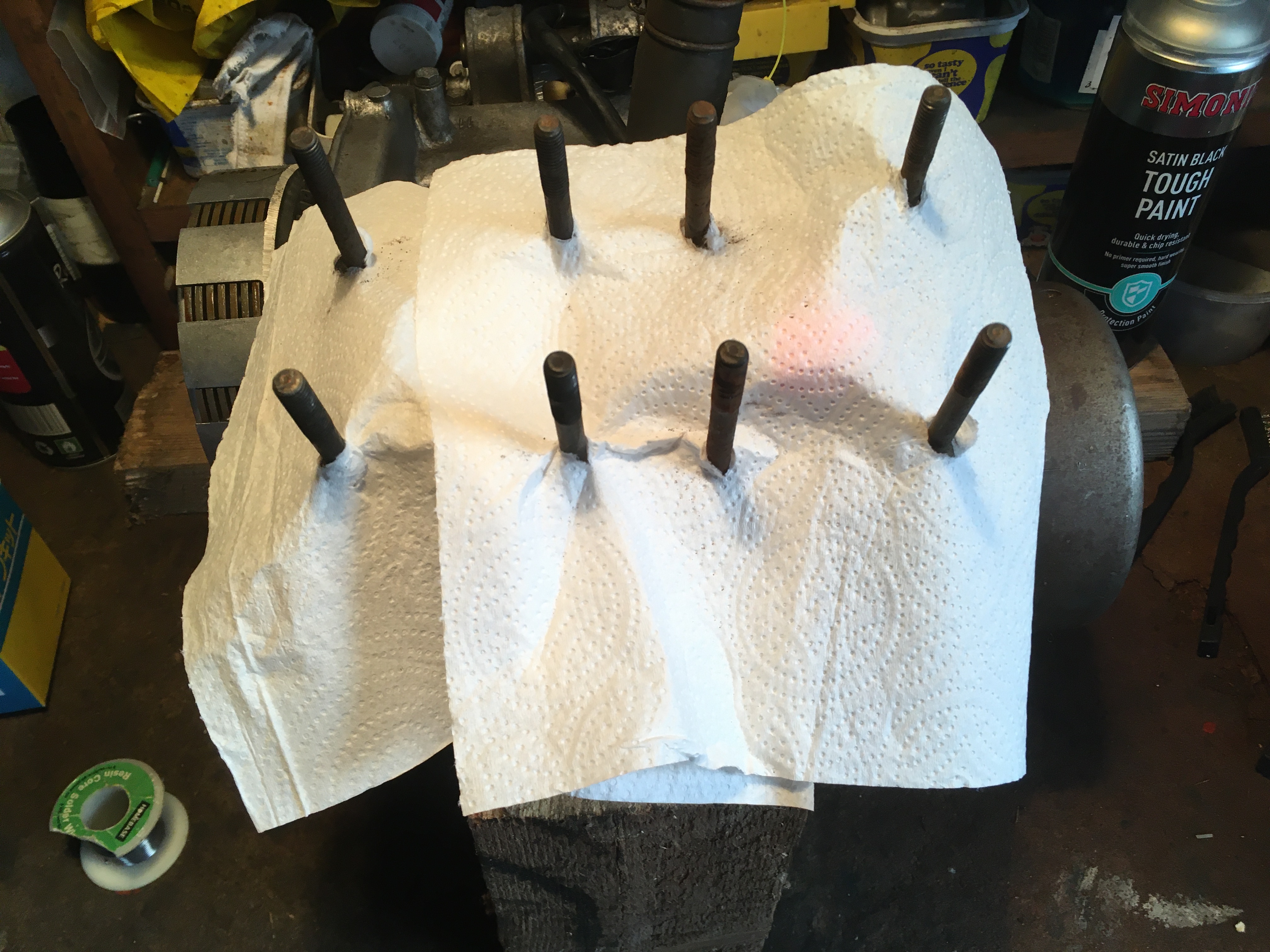
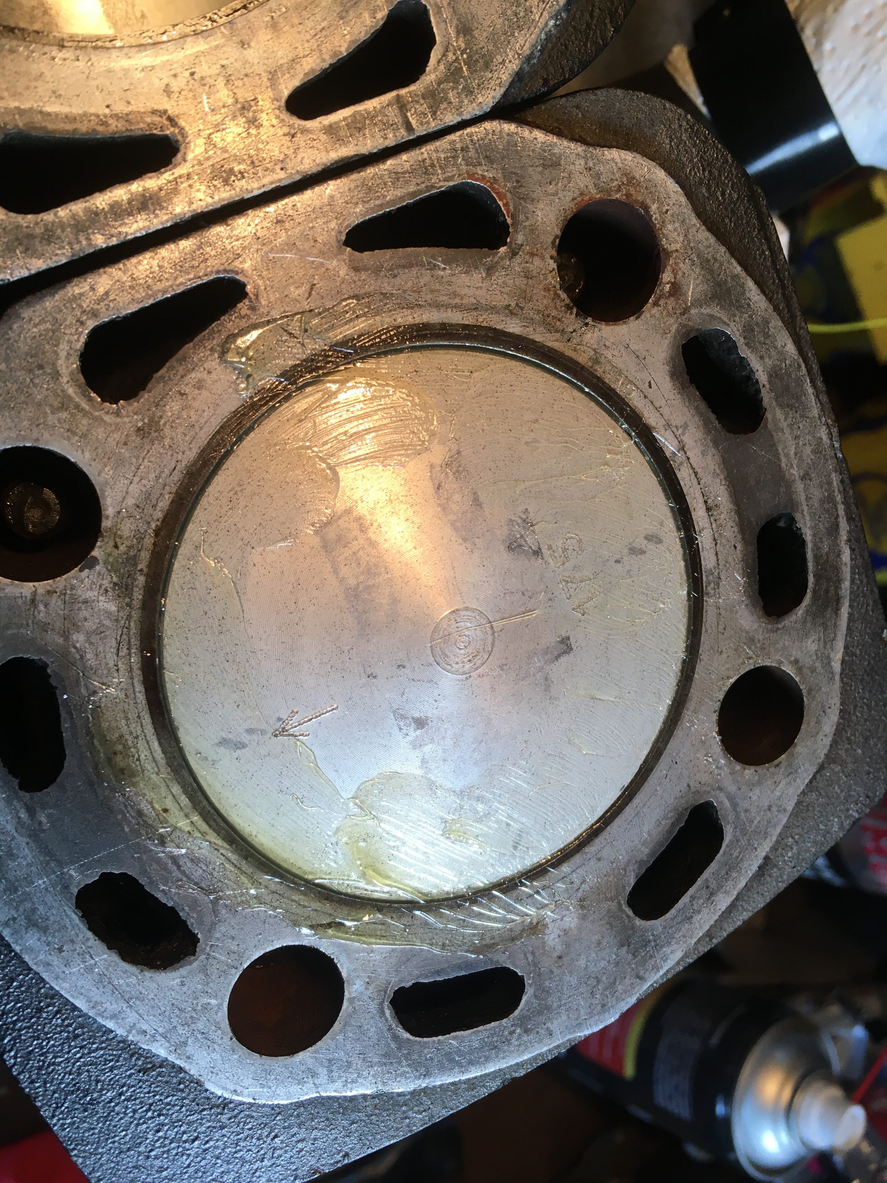
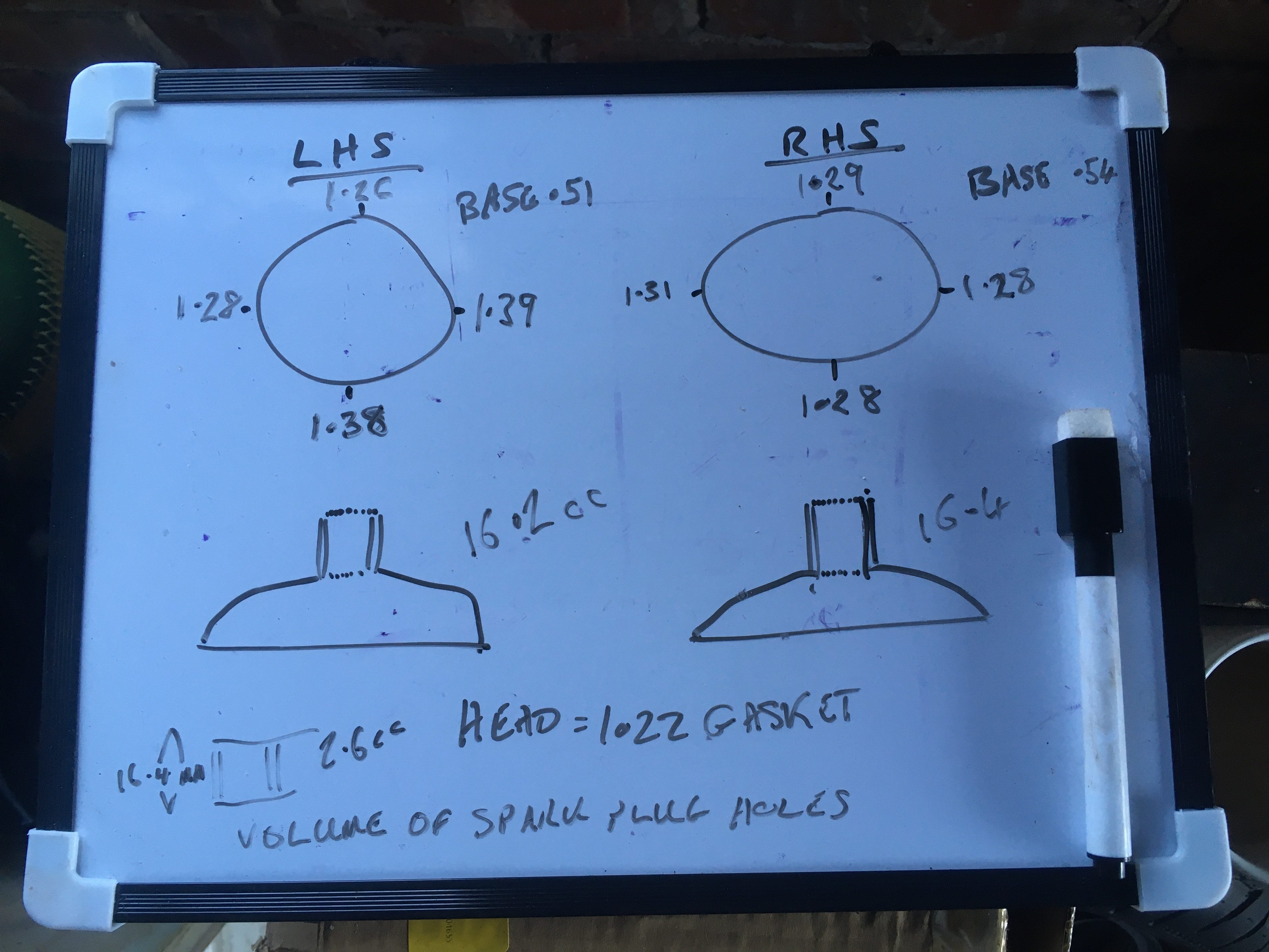
Now I can prep the top end with solder to measure the squish.
The solder I an using is 1.2mm in diameter, and the first build showed only one of the 8 dimensions had been compressed.
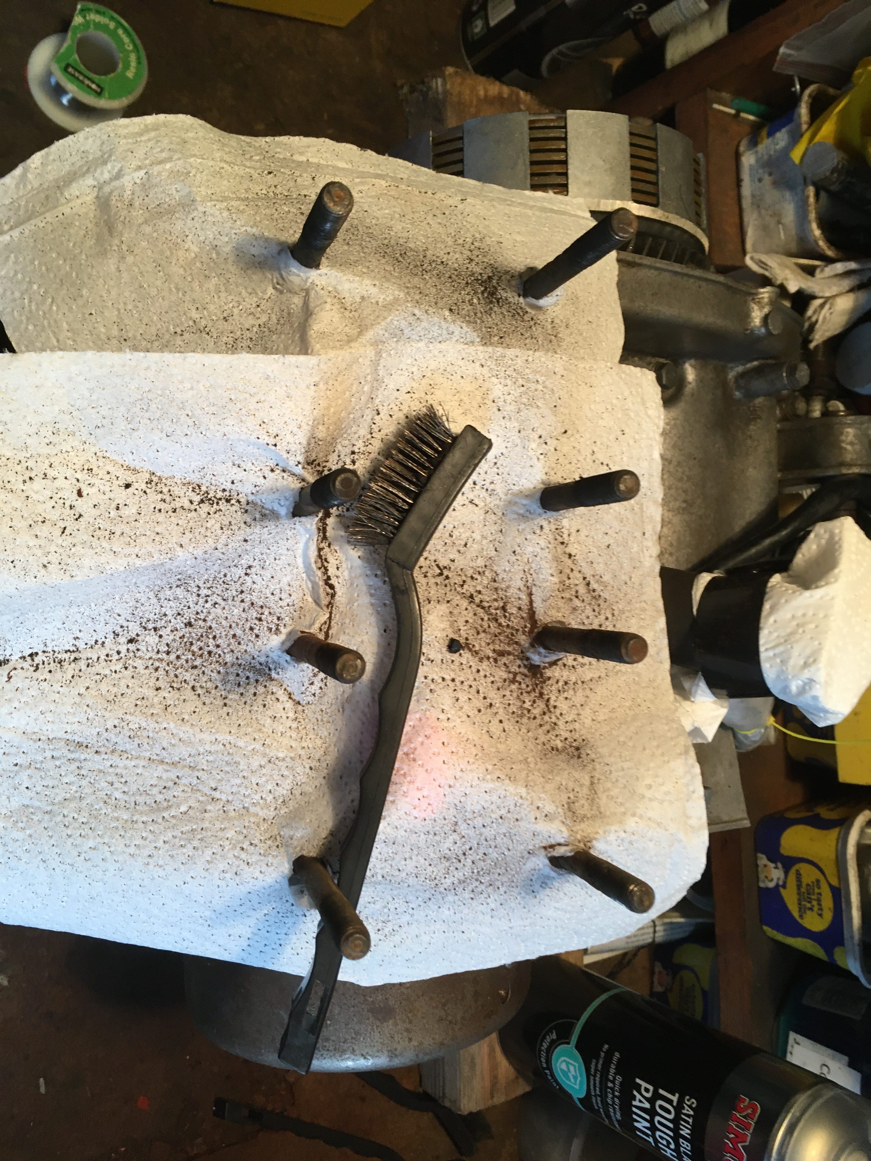
For the next build, I twisted two bits of solder together to have a greater diameter.
It is good practice to measure at 4 places on the rim of the pistons at the same time, to avoid any effect from piston rocking in the bore.
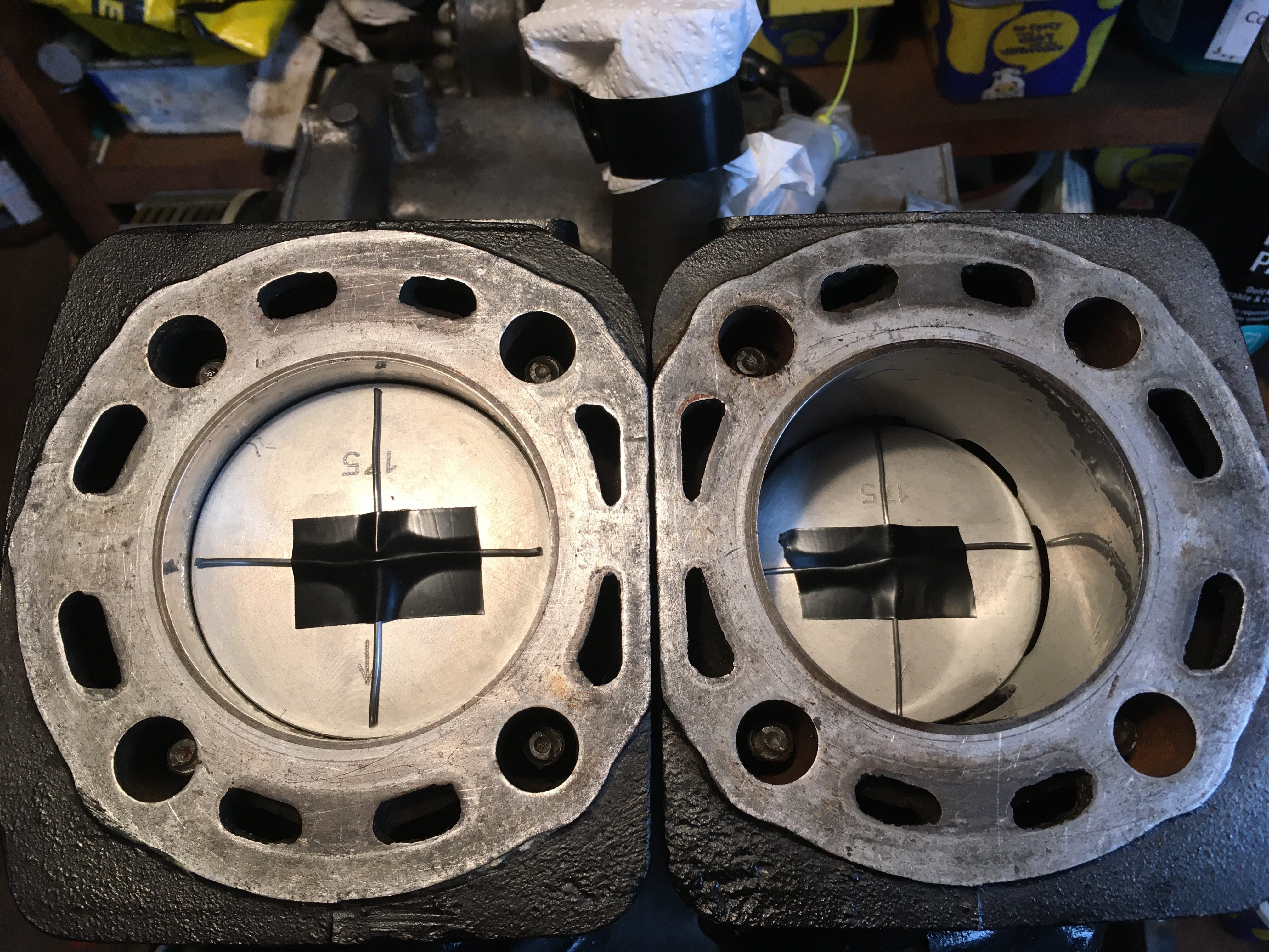
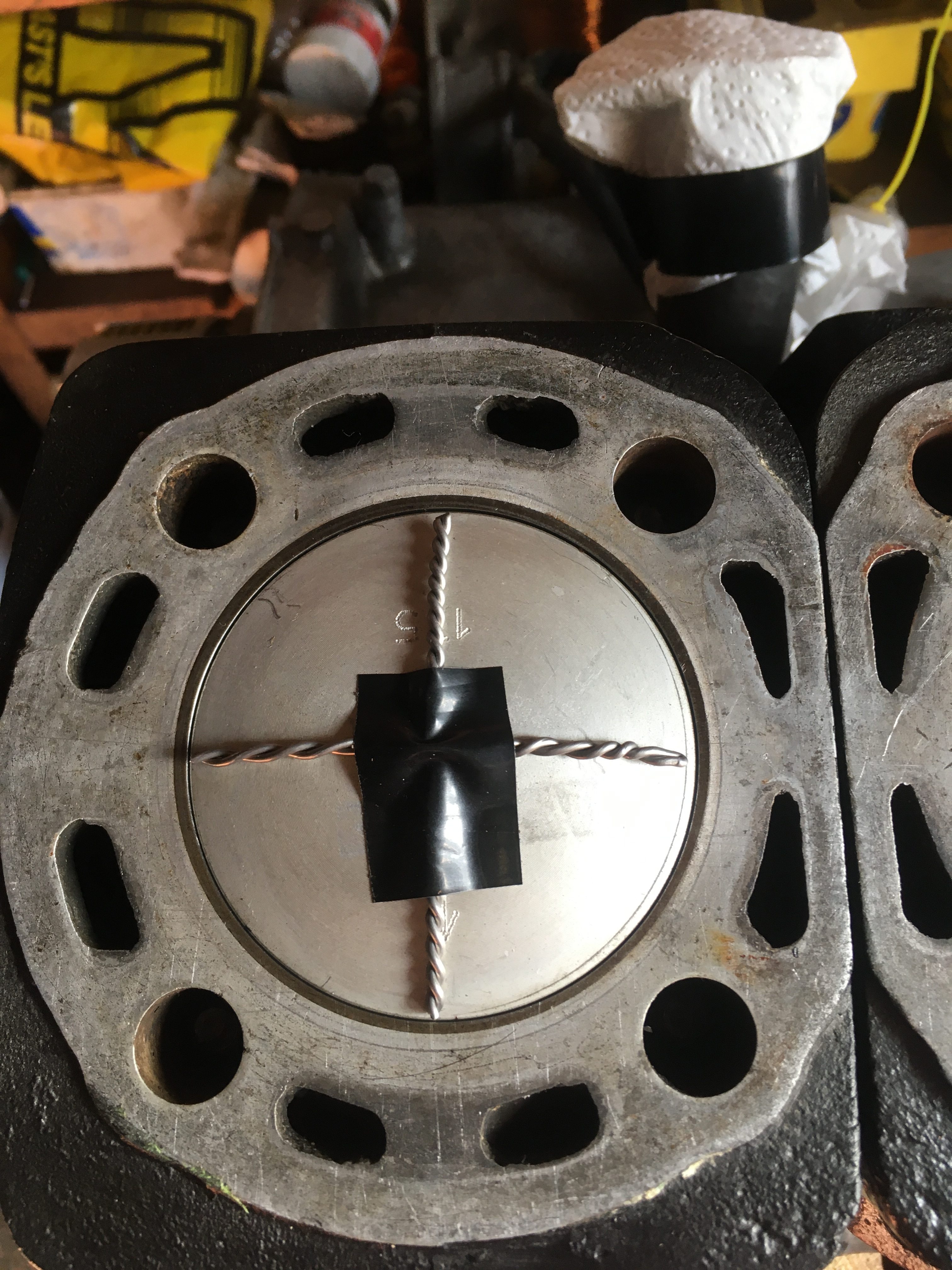
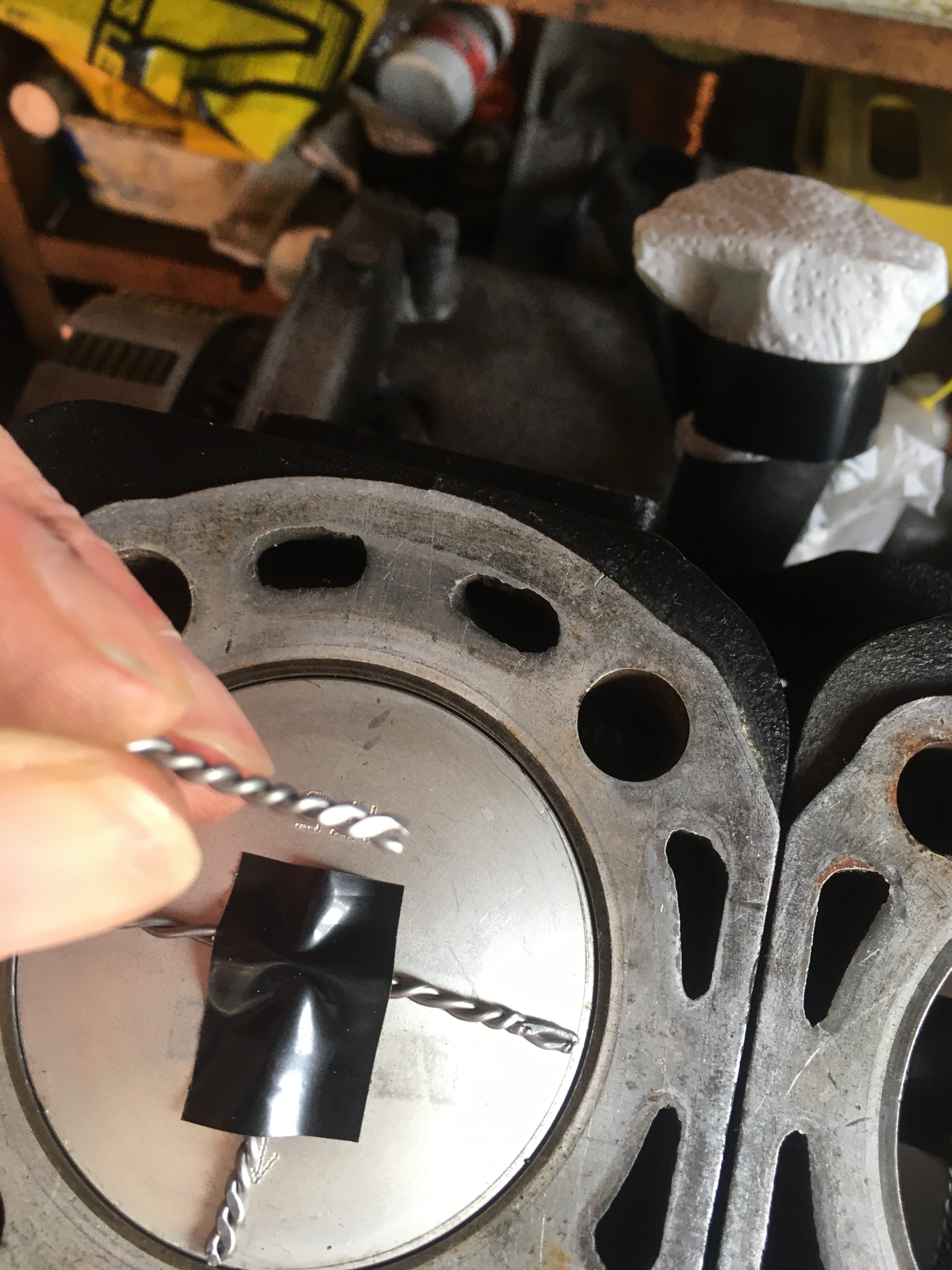
Using the twisted solder, I retrieved good readings from flattened solder from all 8 points around the pistons. all 8 measurements are within 0.1mm in the range of 1.28 to 1.39mm.
This is a very slightly wider squish gap tan ideal. I would have preferred 1.1 to 1.3mm, but it’s close enough, and means I don’t need to use custom base gasket thicknesses.
Now I can proceed to measuring the compression ratio.
On a 4-stroke, the compression ratio is given as swept volume against combustion chamber volume. By convention, no attention is given to the valve timing, which should probably be the case, a compression doesn’t start until the exhaust valve is fully closed.
On a 2-stroke, the convention is to quote the “trapped” compression ratio. That is the swept volume from the exhaust port closing to Top Dead Centre.
This is why CR should be measured after optimising the squish, as moving the barrel up and down will change the exhaust port height above the crankcases, and affect the
swept volume above the top of the port.
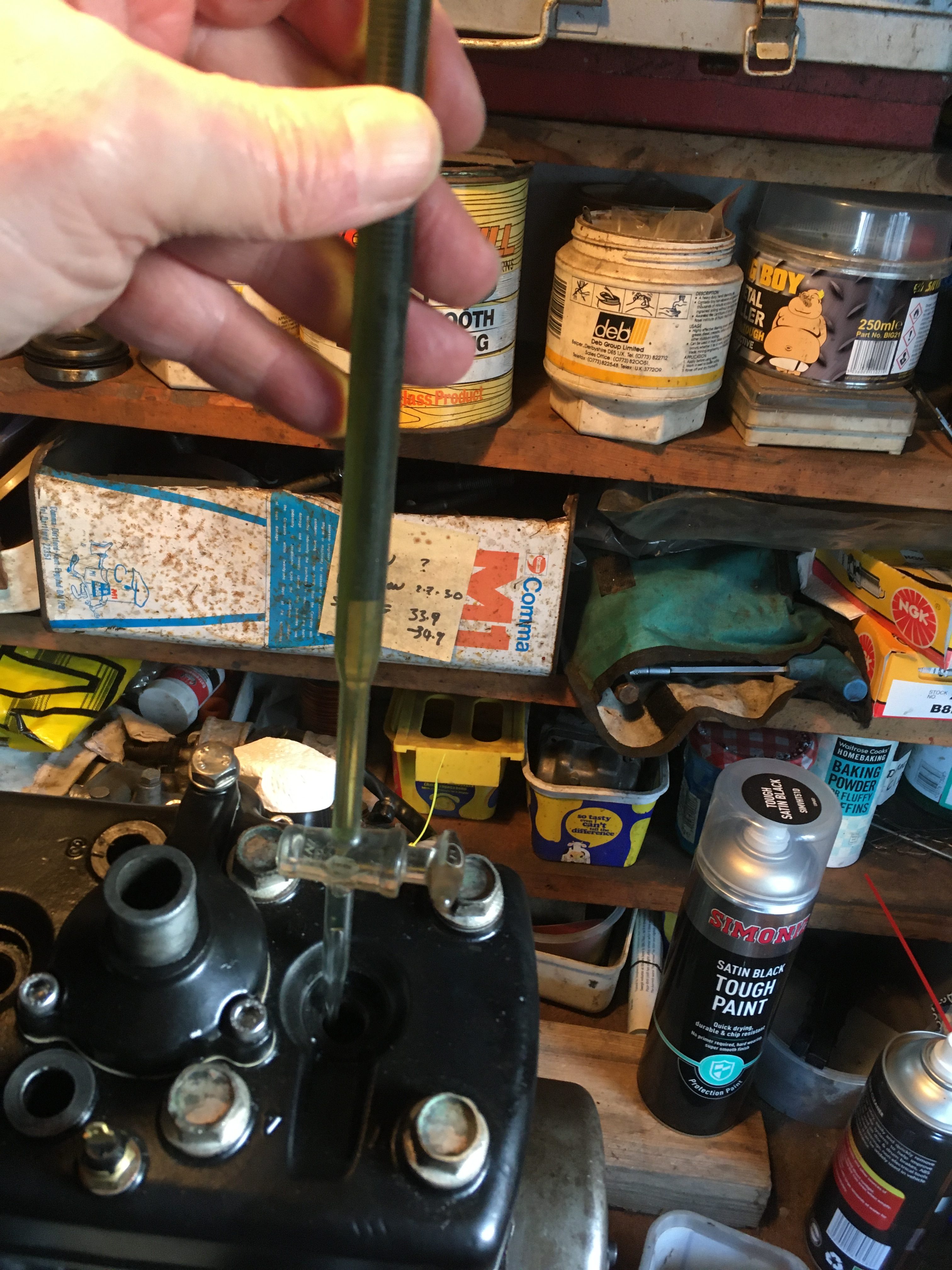
The swept volume can be calculated from the barrel measurements, but the combustion chamber needs to be measured, and we do this by building up the top end, and filling the combustion chamber with a measured amount of fluid.
I use a mix of paraffin and 2-stroke oil, thin enough to drip from a burette, but thick enough so that it hopefully, wont disappear down the sides of the piston.
If you lack a burette, a syringe can be used, but I find a burette to be more accurate.
1. Move the piston to top dead centre.
2. Wipe some grease around the edges of the piston to seal the bore as much as possible.
3. Bolt up the head and gasket, torquing down to the recommended 17 to 18 ft/lb.
4. Fill the combustion chamber with fluid, to the top of the plug hole.
5. Note down the amount of fluid you have used from the burette/syringe.
6. Rotate the crank, and catch the fluid as it runs out of the exhaust port.
7. Do the other side.
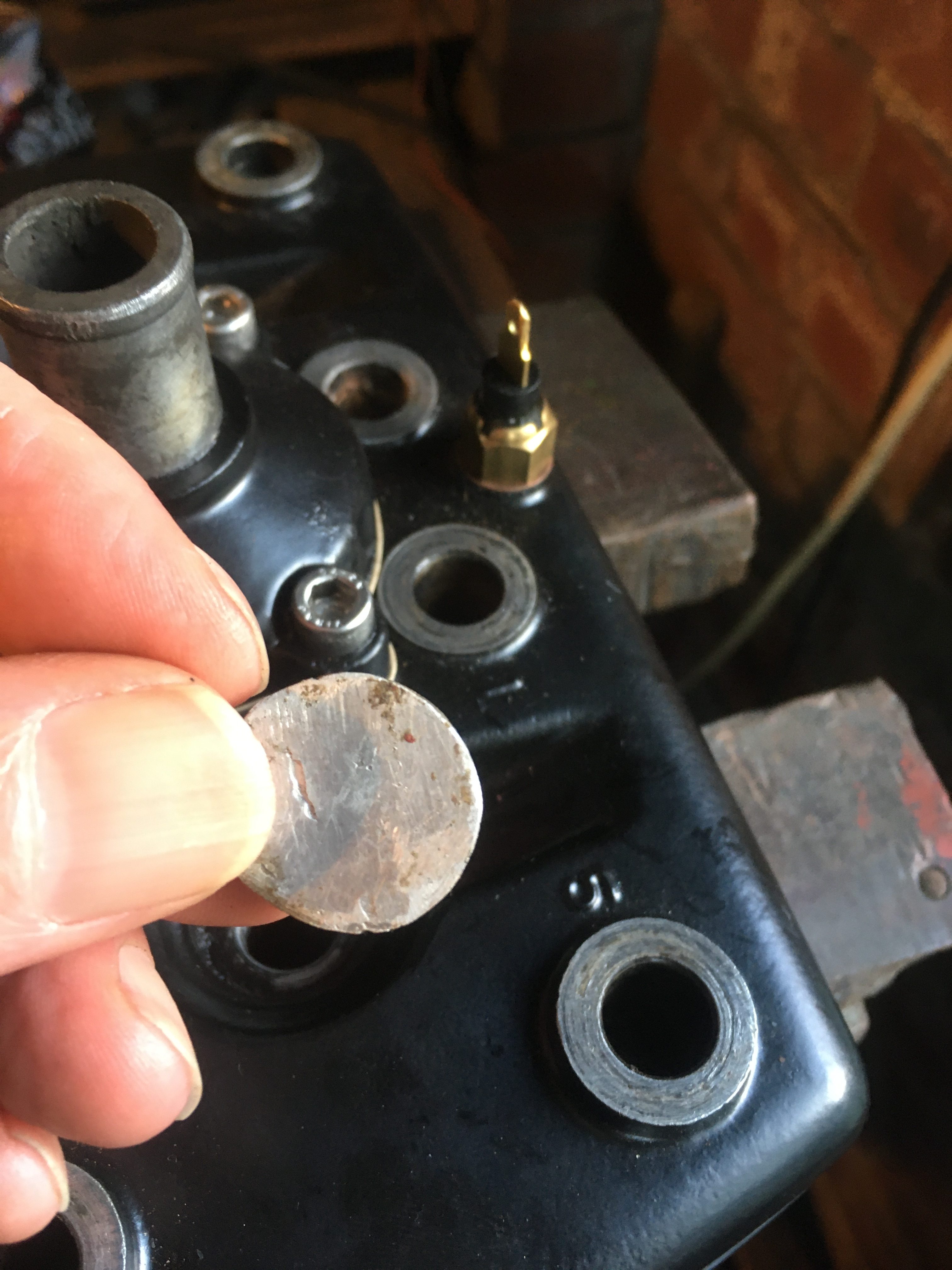
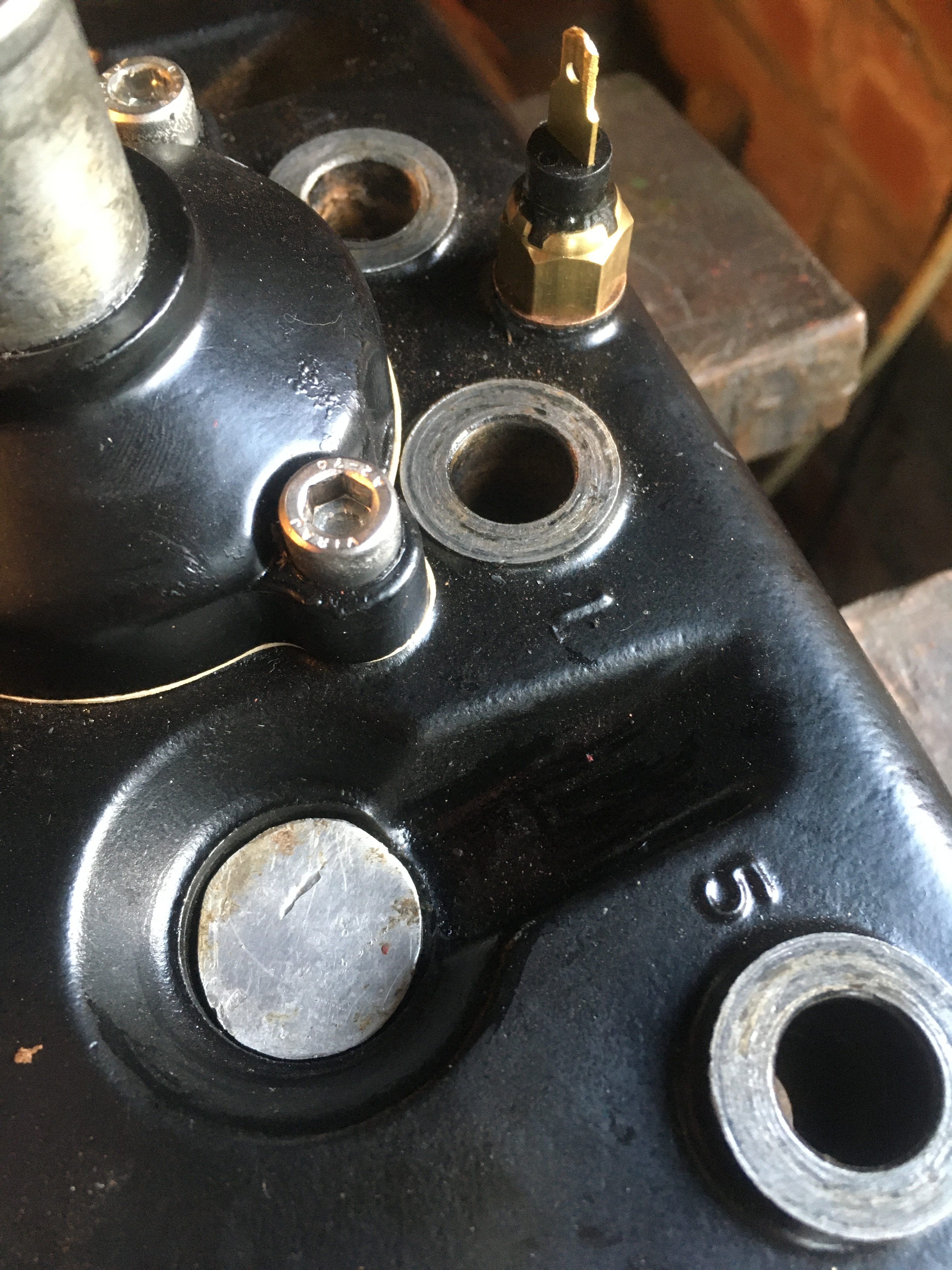
Now you need to subtract the amount of fluid held in the plug hole.
You can calculate this, but I prefer to measure using the burette.
To this end, I have a little disk of aluminium plate which I can stick to cover the exhaust hole end with grease, or more reliably, some silicon gasket goo.
Now I have all my measurements, and I can proceed to plug them into the spreadsheet I prepared earlier 🙂
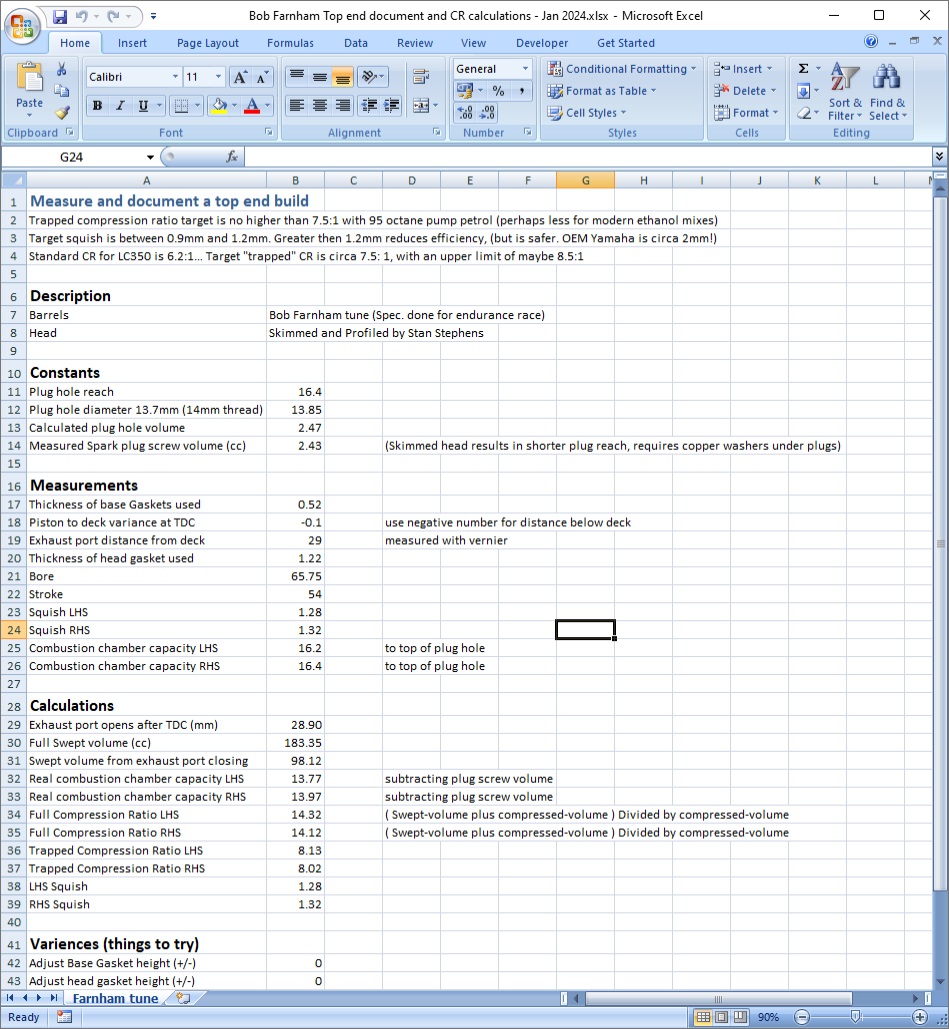
With my squish of circa 1.3mm, my compression ratio works out at just over 8:1.
Perhaps the CR is a little high, but this engine ran and was abused for over 10k miles in the past, and even with a different bottom end, potentially, different gasket sizes by a few fractions of a millimetre, it cant be that far out.
So this is how it will be built up